Orthopedic joint device and control method thereof

A joint and orthopedic technology, used in non-surgical orthopedic surgery, medical science, prosthesis, etc., to achieve the effect of precise support

Active Publication Date: 2021-08-24
OTTO BOCK HEALTHCARE IP GMBH & CO KG
View PDF8 Cites 0 Cited by
  • Summary
  • Abstract
  • Description
  • Claims
  • Application Information

AI Technical Summary

Problems solved by technology

Another disadvantage is that after a certain exercise has started, the user is forced to carry out the started exercise even when the situation changes or the user's wishes change.

Method used


Image

  • Orthopedic joint device and control method thereof
  • Orthopedic joint device and control method thereof
  • Orthopedic joint device and control method thereof

Examples


Embodiment Construction

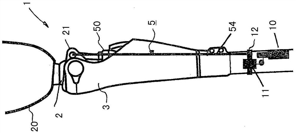
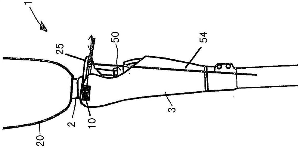
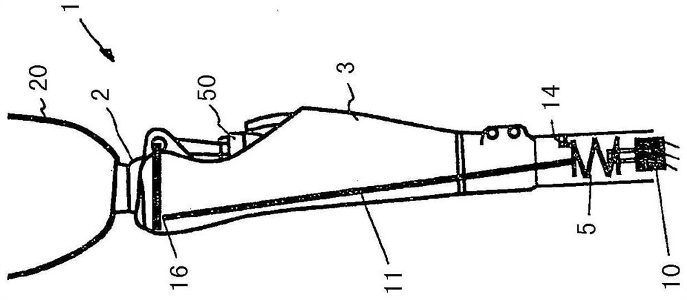
[0033] figure 1 An orthopedic joint device in the form of a prosthetic knee joint is shown, with an upper part 2 on which a thigh sleeve 20 is arranged for receiving a thigh stump. The lower part 3 is articulated distally relative to the upper part 2 so that the upper part 2 can pivot relative to the lower part 3 . On the rear side of the upper part 2 a bracket 21 is formed, on which a damping device 50 in the form of a hydraulic or pneumatic damper is arranged on the one hand and an energy store 54 in the form of an elastic tendon on the other hand. The elastic tendon is connected via a variable speed transmission 11 to an actuator 10 in the form of an electric motor. The electric motor is arranged in a shank tube which is fastened to the lower part 3 . An accumulator 54 in the form of an elastic tendon is fixed to the variable speed transmission 11 and to the carriage 12, an electric motor is activated which acts on the carriage 12 via the variable speed transmission 11 an...


PUM


Abstract

The invention relates to a method for controlling an orthopedic joint device (1) of a lower limb, which has an upper part (2) and a lower part (3) articulated on the upper part, on which A conversion device (5) is arranged between the part and the lower part, by means of which during the swinging of the upper part (2) relative to the lower part (3) the mechanical work resulting from this relative movement is converted and stored in at least one accumulator In the energy device (54) and re-input to the joint device (1) with a time offset in order to support the relative movement, wherein the stored energy is inverted and carried out in a controlled manner during the support of the relative movement input of mechanical work.

Description

technical field [0001] The invention relates to a method for controlling an orthopedic articulation device of the lower limbs, which has an upper part and a lower part articulated on the upper part, between which a switching device is arranged, by means of which During the pivoting of the upper part relative to the lower part, the conversion device converts the mechanical work from this relative movement and stores it in at least one energy store and reintroduces it to the joint device with a time offset in order to support the relative movement . The invention also relates to an orthopedic technical joint device for the lower limbs, with an upper part and a lower part articulated on the upper part, between which a switching device is arranged, by means of which switching device the upper part During the pivoting of the lower part, the mechanical work resulting from this relative movement is converted, stored in at least one energy store and reintroduced to the joint device w...

Claims


Application Information

Patent Timeline
Patent Type & Authority Patents(China)
IPC IPC(8): A61F2/60A61F2/68
CPCA61F2002/5006A61F2002/5072A61F2002/708A61F2/604A61F2/64A61F2/70A61F2/74A61F2005/0155A61F2005/0167A61F2005/0179A61F2002/701A61F2002/5073A61F2002/5075A61F5/0125A61F2002/503A61F2005/0169
Inventor L·莫斯勒M·普施A·帕佩C·威尔
Owner OTTO BOCK HEALTHCARE IP GMBH & CO KG
Why Eureka
Try Eureka