Fluid control valve utilizing shape memory alloy driving spring

a technology of shape memory and driving spring, which is applied in the direction of lift valves, valve details, instruments, etc., can solve the problems of high cost, high complexity and manufacturing cost of patented pump drive of this patent, and expensive valves that may be difficult to produce and maintain, etc., to achieve accurate and controllable flow regulation, dramatic valve rotation, and slow change rate

Inactive Publication Date: 2017-01-05
A RAYMOND & CO
View PDF9 Cites 0 Cited by
  • Summary
  • Abstract
  • Description
  • Claims
  • Application Information

AI Technical Summary

Benefits of technology

[0019]Regardless of the embodiment, the shape memory alloy valve of the disclosed inventive concept allows for gradual and regulated changes in the position of the valve for accurate and controllable flow regulation. The speed of rotation of the valve may be adjusted by selecting between a number of variables that include, for example, thickness and length of the shape memory alloy spring. As a particular example, a thicker coil would allow for a slower rate of change based on changes in temperature. A longer spring would effect a more dramatic rotation of the valve when subjected to a temperature change. A specific selection of the material being alloyed would also achieve a more controlled movement of the spring over a given temperature change. If the temperature of the shape memory alloy spring is changed according to an electric current, the amount of current may be selectively varied to achieve a specific shape change in the spring.

Problems solved by technology

A set of concentric (inner and outer) tubes [124, 126] having matching facing helical slots [130] with bearings [132] therebetween is provided to convert the reciprocating linear motion into reciprocating rotary motion.” The patented pump drive of this patent is thus highly complex and costly to manufacture.
The patented variable pressure valve of this patent is also highly complex and costly to manufacture.
As the above-discussed references illustrate, known fluid control valves that incorporate shape memory alloy biasing elements are either ineffective at translating linear motion into rotary motion or are of complex designs and have numerous parts, both aspects contributing to an expensive valve that may be difficult to produce and maintain.
In addition, known valves do not provide for gradual changes in the position of the valve in response to certain conditions, such as temperature.

Method used


Image

  • Fluid control valve utilizing shape memory alloy driving spring
  • Fluid control valve utilizing shape memory alloy driving spring
  • Fluid control valve utilizing shape memory alloy driving spring

Examples


first embodiment

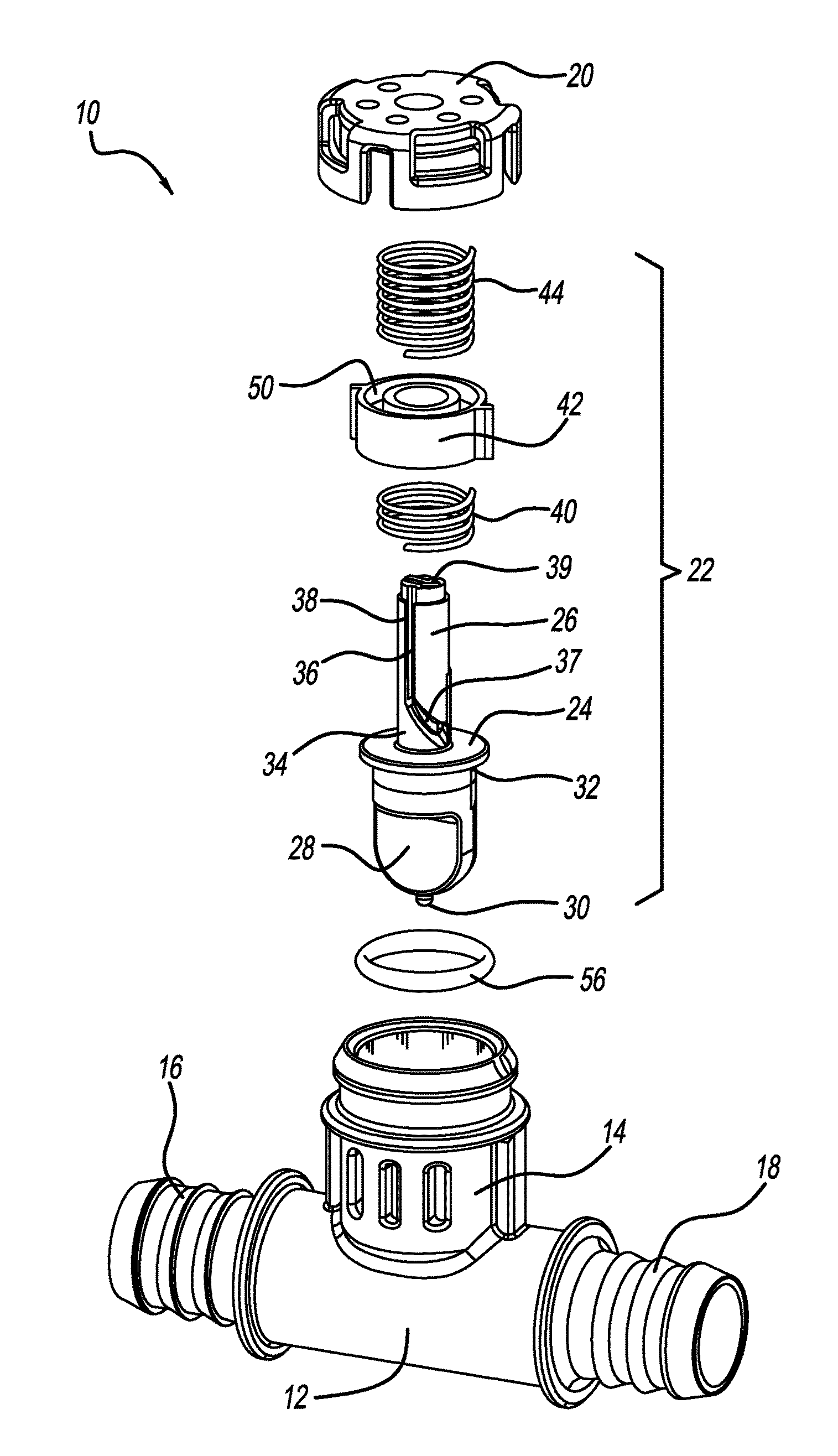
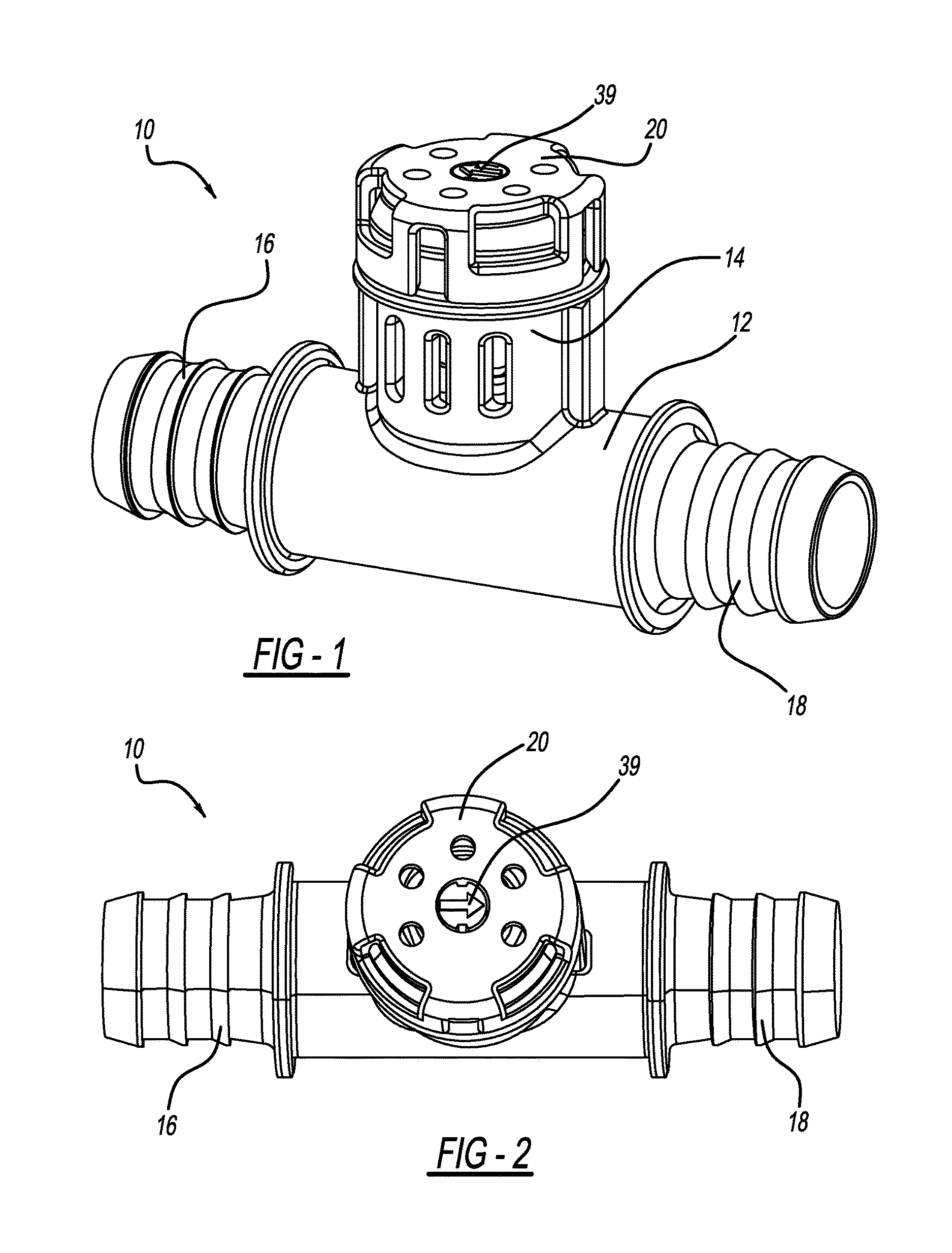
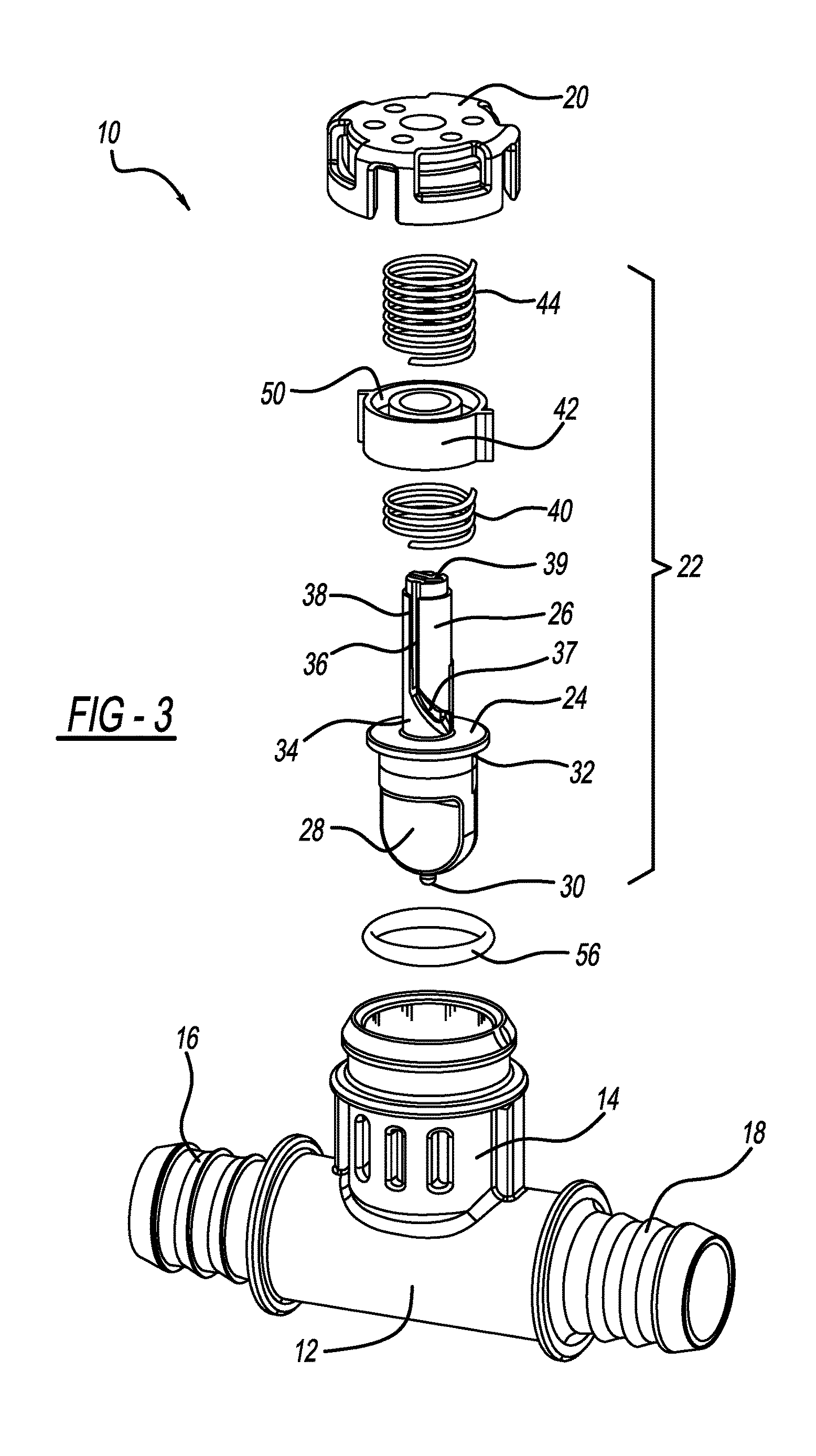
[0044]FIGS. 1 through 10 illustrate the valve of the disclosed inventive concept, generally illustrated as 10. The valve 10 may be used in any environment where the flow of a liquid or a gas needs to be selectively regulated. The valve 10 includes a substantially T-shaped body 12 having a valve assembly cylinder 14, a first port 16 and a second port 18. Of the first port 16 and the second port 18, one is an inlet port and the other is an outlet port. The long axis of the first port 16 is aligned with the long axis of the second port 18, though this is not necessarily the case. As further illustrated in these same figures, the first port 16 and the second port 18 are disposed at right angles with respect to the valve assembly cylinder 14, though this is also not necessarily the case.

[0045]The valve 10 further includes a valve assembly cap 20. The valve assembly cap 20 is preferably snap-fitted to the valve assembly cylinder 14, though it may also be attached to the valve assembly cyl...

second embodiment

[0057]FIGS. 11 and 11A illustrate the shape memory alloy valve according to the disclosed inventive concept, generally illustrated as 100. FIG. 11 illustrates a longitudinal sectional view of the shape memory alloy valve 100. FIG. 11A illustrates a view of the shape memory alloy valve 100 taken along line 11A-11A of FIG. 11.

[0058]Like the shape memory alloy valve 10 discussed above, the shape memory alloy valve 100 may be used in any environment where the flow of either a liquid or a gas needs to be selectively regulated. The valve 100 includes a substantially T-shaped body 102 having a valve assembly cylinder 104, a first port 106 and a second port 108. Of the first port 106 and the second port 108, one is an inlet port and the other is an outlet port. The long axis of the first port 106 is aligned with the long axis of the second port 108, though this is not necessarily the case. As further illustrated in these same figures, the first port 106 and the second port 108 are disposed ...

third embodiment

[0064]FIGS. 12 through 20 illustrate the valve of the disclosed inventive concept, generally illustrated as 200. As described above with respect to the shape memory alloy valves 10 and 100, the shape memory alloy valve 200 may be used in any environment where the flow of a either a liquid or a gas needs to be selectively regulated.

[0065]The valve 200 includes a substantially T-shaped body 202 having a valve assembly cylinder 204, a first port 206 and a second port 208. Of the first port 206 and the second port 208, one is an inlet port and the other is an outlet port. The long axis of the first port 206 is aligned with the long axis of the second port 208, though this is not necessarily the case. As further illustrated in these same figures, the first port 206 and the second port 208 are disposed at right angles with respect to the valve assembly cylinder 204, though this is also not necessarily the case.

[0066]The valve 200 further includes a non-rotatable valve assembly cap 210. Th...


PUM


Abstract

A fluid control valve having a shape memory alloy spring for moving the valve member between an open position and a closed position is provided. The valve includes a valve assembly cylinder, a valve assembly cap fitted to the cylinder, a fluid inlet and a fluid outlet associated with the cylinder, a first member having a cam follower groove, a second member having a cam operatively associated with the groove, a fluid flow gate associated with one of the members as well as the inlet and the outlet, a return spring associated with one of the members, and the shape memory alloy spring associated with one of the members. The length of the shape memory alloy spring changes in response to changes in temperature. The first member is either a rotating valve or a reciprocating member. The second member is either a reciprocating ring or a rotating valve cylinder.

Description

TECHNICAL FIELD[0001]The disclosed inventive concept relates generally to control valves for regulating the flow of fluids. More particularly, the disclosed inventive concept relates to a fluid control valve having a shape memory alloy spring that provides the driving force for the movement of the valve.BACKGROUND OF THE INVENTION[0002]Control valves for the regulation of fluid flow are found in a great variety of applications in a wide array of industries. For example, in automotive vehicles, fluid control valves are used in the regulation of both lubricant and coolant flow.[0003]The conventional fluid control valve includes a valve body having a valve assembly cylinder, an inlet port and an outlet port. The conventional fluid control valve further includes a rotatably movable valve positioned within the valve assembly cylinder of the valve body. The rotatably movable valve includes a valve stem and a gate or cone or other means for interfering with the flow of a fluid through the ...

Claims


Application Information

Patent Timeline
Patent Type & Authority Applications(United States)
IPC IPC(8): F16K31/00F16K1/22
CPCG05D23/026F16K31/5282F16K31/002F16K1/221
Inventor JACKSON, NICHOLASRAYMOND, ALBERT
Owner A RAYMOND & CO
Why Eureka
Try Eureka