Automatic uncapping equipment for beverage bottles
An automatic cap opening and beverage bottle technology, which is applied in the dismantling of flange caps, etc., can solve problems such as unsuitable for general use, easy to damage the bottle mouth, large size and inconvenient maintenance, etc., and achieve the effect of saving manpower and improving efficiency
- Summary
- Abstract
- Description
- Claims
- Application Information
AI Technical Summary
Problems solved by technology
Method used
Image
Examples
Embodiment 1
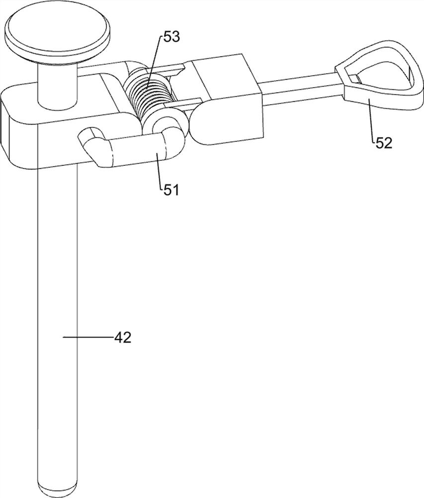
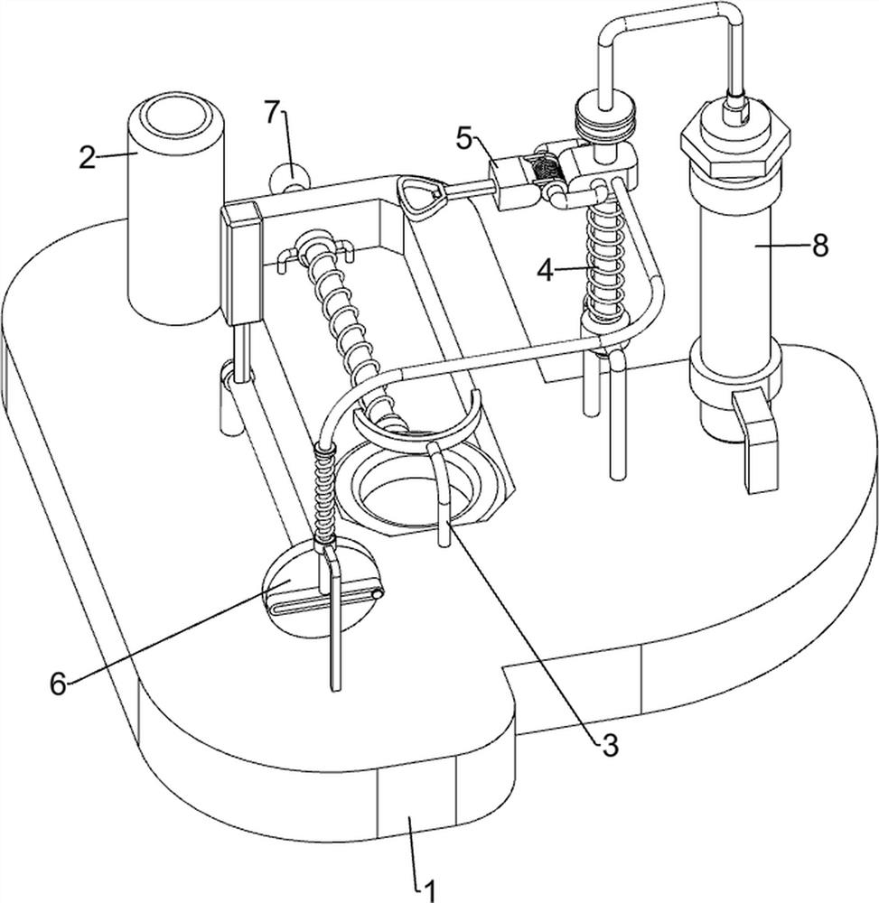
[0027] A kind of beverage bottle automatic uncapping equipment, such as Figure 1-Figure 3 As shown, it includes a base 1, a straw tank 2, a first fixed rod 3, a lifting mechanism 4 and a cover opening mechanism 5, the upper rear side of the base 1 is provided with a straw tank 2, and the upper middle of the base 1 is provided with a first fixed rod 3, The right side of the base 1 is provided with a lifting mechanism 4, and the lifting mechanism 4 is provided with a cover opening mechanism 5.
[0028] When people need to uncap the beverage bottle, people can place the beverage bottle that needs to be uncapped on the base 1, and then people can press the lifting mechanism 4 downward, and the downward movement of the lifting mechanism 4 will drive the uncapping mechanism 5 downward. Move, when uncapping mechanism 5 moves downwards to engage with bottle cap, people can make elevating mechanism 4 move upwards, and then uncapping mechanism 5 can move upwards, so just bottle cap can...
Embodiment 2
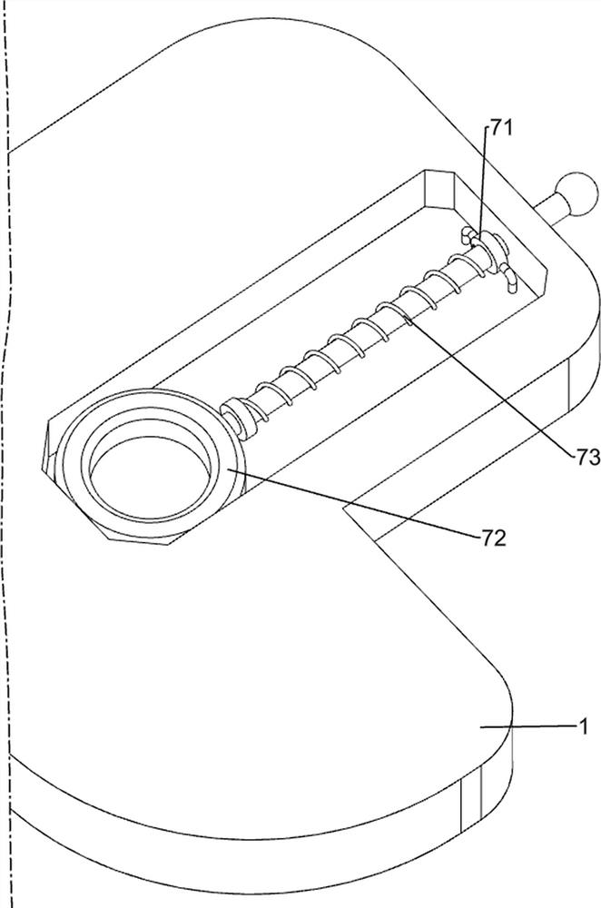
[0034] In a preferred embodiment of the present invention, as Figure 4-Figure 6 As shown, a fixing mechanism 6 is also included. The fixing mechanism 6 includes a third support rod 61, a first connecting rod 62, a second spring 63, a fourth support rod 64, a rotating shaft 65 and a second fixing rod 66. On the base 1 The front side is provided with a third support rod 61, on which the third support rod 61 is slidably provided with a first connecting rod 62, the first connecting rod 62 is connected with the elevating rod 42, and a second spring 63 is sleeved on the first connecting rod 62 , the two ends of the second spring 63 are respectively connected to the third support rod 61 and the first connection rod 62, the left side of the upper middle part of the base 1 is provided with a fourth support rod 64, and the fourth support rod 64 is rotatably connected with a rotating shaft 65 The front side of the rotating shaft 65 is in contact with the first connecting rod 62 , and th...
PUM
 Abstract
Description
Claims
Application Information
 - R&D
- Intellectual Property
- Life Sciences
- Materials
- Tech Scout
- Unparalleled Data Quality
- Higher Quality Content
- 60% Fewer Hallucinations
Browse by: Latest US Patents, China's latest patents, Technical Efficacy Thesaurus, Application Domain, Technology Topic, Popular Technical Reports.
© 2025 PatSnap. All rights reserved.Legal|Privacy policy|Modern Slavery Act Transparency Statement|Sitemap|About US| Contact US: help@patsnap.com


