Damping power cabinet capable of effective dehumidification

A technology for power cabinets and shock-absorbing springs, applied in anti-seismic equipment, electrical components, substation/distribution device shells, etc., can solve problems such as poor shock absorption effect, poor transparency, and affecting the accuracy of observation, and improve heat utilization efficiency, reduce heat loss, and avoid friction debris

Inactive Publication Date: 2018-02-16
合肥名龙电子科技有限公司
View PDF0 Cites 19 Cited by
  • Summary
  • Abstract
  • Description
  • Claims
  • Application Information

AI Technical Summary

Problems solved by technology

[0002] The power cabinet is a storage device for storing voltmeters, ammeters or other electrical equipment, and is used to protect these equipment from short circuits, bumps and other accidents. In the prior art, in order to facilitate the staff to observe the internal components of the switch cabinet For operating conditions, a closed plastic observation hole is usually set on the door of the switch cabinet, but since the observation hole is made of plastic and is integrated with the door, this not only causes inconvenience in observation and temperature measurement, It will also affect the accuracy of observation due to the poor transparency of the observation window. During the use of the power cabinet, there will often be too much dust inside, which will affect the normal operation of the power devices, resulting in failure of the power system and extreme It is very inconvenient; most of the bases of existing shock-absorbing power cabinets use simple shock-absorbing springs for shock absorption. Although they can meet their use requirements, the shock-absorbing effect is prone to be poor, and it is easy to cause the shock-absorbing base and There is a collision between the power cabinets, and the base is fixed unstable

Method used


Image

  • Damping power cabinet capable of effective dehumidification
  • Damping power cabinet capable of effective dehumidification
  • Damping power cabinet capable of effective dehumidification

Examples


Embodiment Construction

[0021] The following will clearly and completely describe the technical solutions in the embodiments of the present invention with reference to the accompanying drawings in the embodiments of the present invention. Obviously, the described embodiments are only some, not all, embodiments of the present invention. Based on the embodiments of the present invention, all other embodiments obtained by persons of ordinary skill in the art without making creative efforts belong to the protection scope of the present invention.

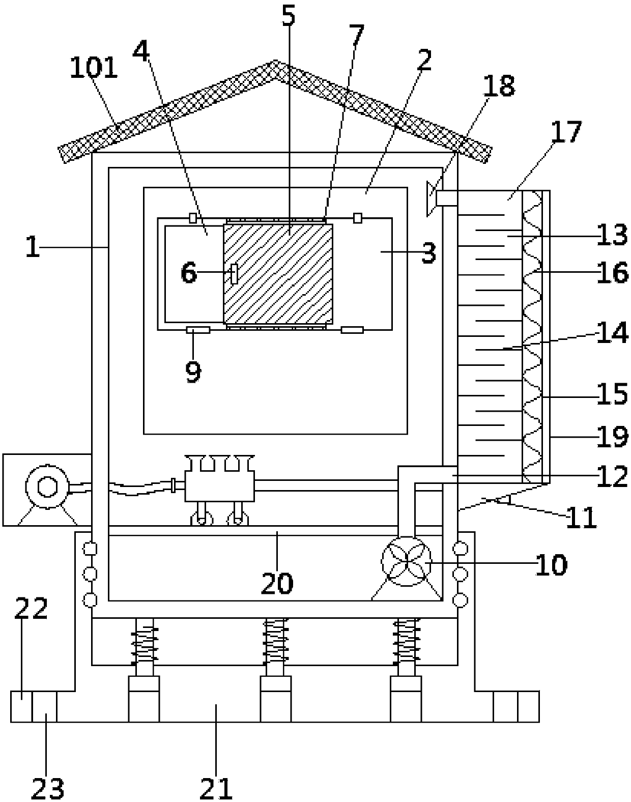
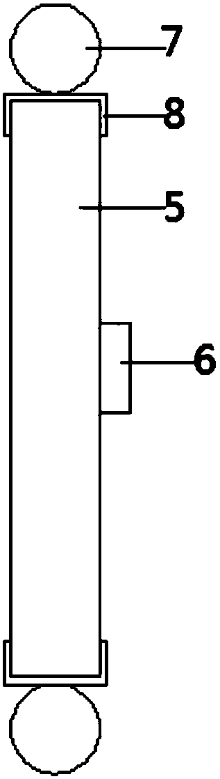
[0022] see Figure 1-2 , in an embodiment of the present invention, a shock-absorbing power cabinet capable of effective dehumidification includes a cabinet body 1 and a rainproof roof 101 arranged on the top of the cabinet body 1, the section of the rainproof roof 101 is V-shaped, and the cabinet There is a cabinet door 2 on the front side of the body 1, and a storage cavity 3 is opened on the cabinet door 2, and an observation window 4 is opened in the area ...


PUM


Abstract

The invention discloses a shock-absorbing power cabinet capable of effectively dehumidifying, comprising a cabinet body and a rain-proof roof arranged on the top of the cabinet body, a cabinet door on the front side of the cabinet body, a storage cavity on the cabinet door, and a An observation window is opened in the storage cavity area, and an observation glass used to open or close the observation window is movably arranged in the storage cavity. The upper end of the seat is fixedly connected to the heat exchange box. The invention is a shock-absorbing power cabinet that can effectively dehumidify, reduces the gap between the observation glass and the cabinet door, can effectively prevent external dust and impurities from entering the power cabinet, and can effectively dehumidify the cabinet. The dust inside the body is collected, and the dust is fully vacuumed, which is convenient to use, can quickly and efficiently remove the moisture in the power cabinet, prolong the service life of the electrical components, and can effectively absorb shock, prevent the base from causing damage to the cabinet, prolong the the service life of the power cabinet.

Description

technical field [0001] The invention relates to the technical field of power equipment, in particular to a shock-absorbing power cabinet capable of effective dehumidification. Background technique [0002] The power cabinet is a storage device for storing voltmeters, ammeters or other electrical equipment, and is used to protect these equipment from short circuits, bumps and other accidents. In the prior art, in order to facilitate the staff to observe the internal components of the switch cabinet For operating conditions, a closed plastic observation hole is usually set on the door of the switch cabinet, but since the observation hole is made of plastic and is integrated with the door, this not only causes inconvenience in observation and temperature measurement, It will also affect the accuracy of observation due to the poor transparency of the observation window. During the use of the power cabinet, there will often be too much dust inside, which will affect the normal op...

Claims


Application Information

Patent Timeline
Patent Type & Authority Applications(China)
IPC IPC(8): H02B1/30H02B1/28H02B1/54
CPCH02B1/306H02B1/28H02B1/303H02B1/54
Inventor 黄思宜
Owner 合肥名龙电子科技有限公司
Why Eureka
Try Eureka