nail puller
A nail puller and chute technology, which is applied in the field of medical devices, can solve the problems that the nail puller is attached to other objects and cannot be clamped independently, so as to achieve the effect of not easy to remove the nail, continuous nail pulling process, and firm nail holding
- Summary
- Abstract
- Description
- Claims
- Application Information
AI Technical Summary
Problems solved by technology
Method used
Image
Examples
Embodiment approach 1
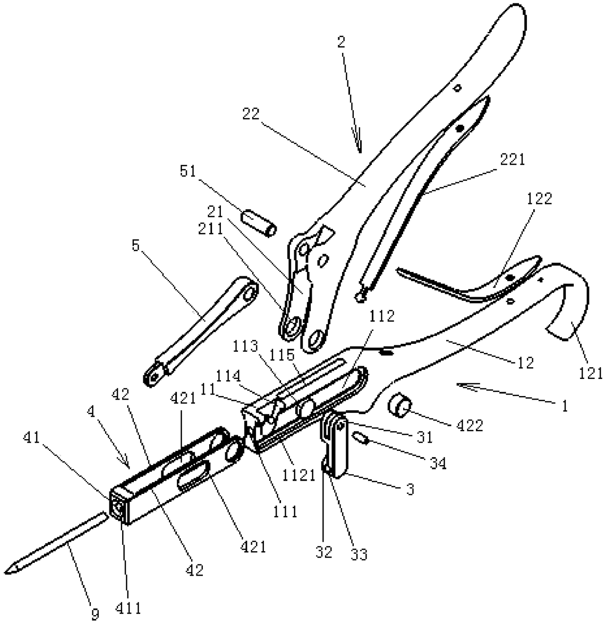
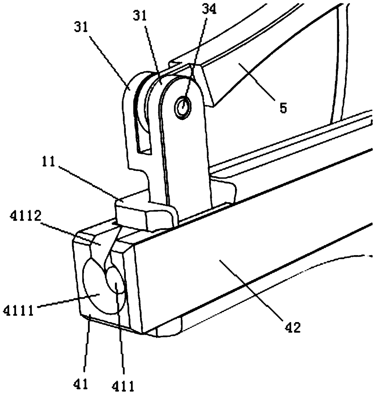
[0034] like figure 1 Shown is an embodiment of the nail puller proposed by the present invention. In Embodiment 1, the nail puller mainly includes: a first pliers body 1 , a locking block 3 , a sliding part 4 , a second pliers body 2 and a connecting rod 5 .
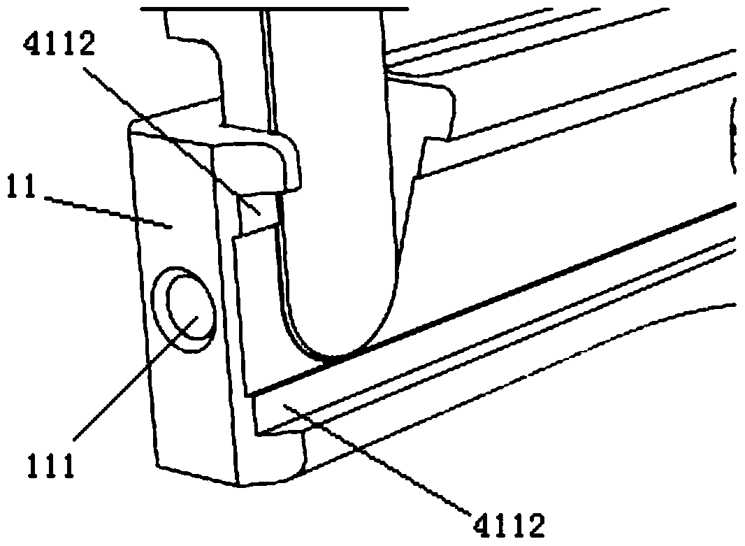
[0035] like figure 1 As shown, in the first embodiment, the first pliers body 1 has a chute portion 11 and a first pliers handle 12 formed at the rear end thereof, and the middle portion of the chute portion 11 is provided with a passage along the longitudinal direction for accommodating the fixing nail. The hole 111 and the two sides of the chute part 11 are provided with opposite chute 112, and the chute 112 is provided with two limiting protrusions 113, which are respectively arranged on the opposite surface of the chute 112, and there is a certain distance between the two limiting protrusions 113 , so that the nail can pass through it. Of course, only setting the limiting protrusion 113 on one side of the chute ca...
Embodiment approach 2
[0045] like Figure 6 Shown, another embodiment of the nail puller of the present invention. In Embodiment 2, the nail puller mainly includes: a first pliers body 6 , a locking block, a sliding part 8 , a pin shaft 7 , a second pliers body and a connecting rod.
[0046] like Figure 6 As shown, in Embodiment 2, the first pliers body 6 has a chute portion and a first pliers handle formed at its rear end, the middle part of the chute portion is provided with a longitudinal via hole, and the two sides of the chute portion are provided with There are opposite sliding grooves, the rear end of the sliding groove part is provided with a long hole 611 passing through transversely, and the front part of the sliding groove part is provided with a locking groove. like Figure 8 As shown, in the second embodiment, a through groove 612 is vertically opened in the middle of the chute portion, and the rear end of the through groove 612 opens at the rear end of the chute portion. The stru...
PUM
 Abstract
Description
Claims
Application Information
 - R&D
- Intellectual Property
- Life Sciences
- Materials
- Tech Scout
- Unparalleled Data Quality
- Higher Quality Content
- 60% Fewer Hallucinations
Browse by: Latest US Patents, China's latest patents, Technical Efficacy Thesaurus, Application Domain, Technology Topic, Popular Technical Reports.
© 2025 PatSnap. All rights reserved.Legal|Privacy policy|Modern Slavery Act Transparency Statement|Sitemap|About US| Contact US: help@patsnap.com


