Lens motors, imaging equipment and mobile terminals
A technology for camera equipment and mobile terminals, which is applied in image communication, TV, color TV components and other directions, can solve the problems of increasing the amount of software correction and synthesis calculation, complex synthesis and correction, and inaccurate correction, and achieves a simplified synthesis and correction process. Improve the user experience and improve the effect of image effects
- Summary
- Abstract
- Description
- Claims
- Application Information
AI Technical Summary
Problems solved by technology
Method used
Image
Examples
Embodiment 1
[0026] In the embodiment of the present invention, the lens motor includes a motor body and a driving device.
[0027] Wherein, the motor body is provided with a plurality of lens mounting positions, for example, two or three lens mounting positions, the number of lens mounting positions matches the number of lenses, and the specific number can be set as required.
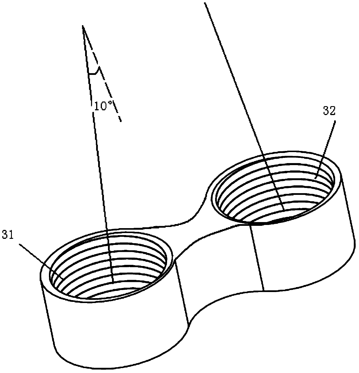
[0028] There is a fixed angle between the central axes of the lens installation positions, for example, the included angle ranges from 0° to 180°. Specifically, the central axes of the lens installation positions can be parallel to each other. After each lens is installed in the corresponding lens mounting position, the optical axes of each lens will also form the same included angle. Each lens can be mounted on the corresponding lens mounting position through screw rotation.
[0029] The driving device is used for driving the lens mounted on the lens mounting position. The driving device is similar to that of th...
Embodiment 2
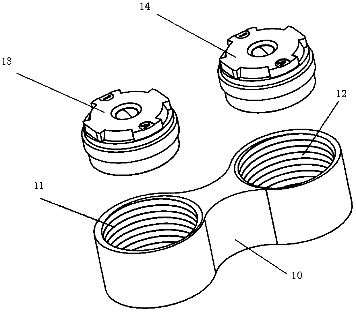
[0032] In this example, if figure 1 As shown, the lens motor includes a motor body 10 and a driving device (not shown in the figure). The motor body 10 is provided with two lens mounting positions 11, 12, the angle between the central axes of the two lens mounting positions is 0°, that is, the two central axes are parallel to each other, when the lenses 13, 14 are mounted on the corresponding lens mounting positions After position, the optical axis of lens 13,14 also can be parallel to each other. Wherein, the lenses 13, 14 can be mounted on the lens mounting positions 11, 12 through screw rotation. The apertures of the lens mounting positions 11 and 12 are the same.
[0033] The driving device in this embodiment may be a common driving unit that can drive the lenses 13 and 14 synchronously. Concretely, if the lens motor is a voice coil motor, then one way of realization may be that the lens mounting positions 11 and 12 use a common coil, and when the energized coil pushes ...
Embodiment 3
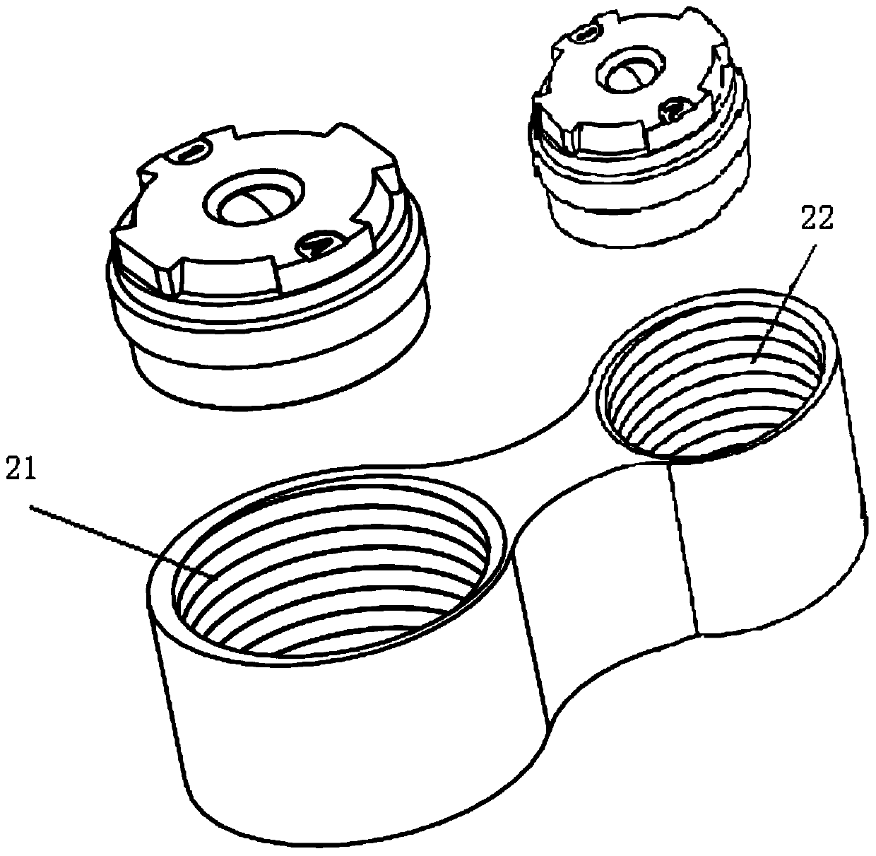
[0036] In this embodiment, the structure of the motor body in the lens motor is similar to the structure of the motor body in the second embodiment, and also has two lens mounting positions, and the central axes of the two lens mounting positions are parallel. However, in this embodiment, if figure 2 As shown, the apertures of the two lens installation positions 21 and 22 are different, so as to install lenses with different diameters. In other embodiments, when there are more than two lens mounting positions on the motor body, the apertures of some of the lens mounting positions may be the same, and the apertures of the remaining lens mounting positions may be different, so that lenses with different diameters may be set according to needs to achieve different shooting Function.
[0037] The driving device of the lens motor may be the same as that in the second embodiment.
PUM
 Abstract
Description
Claims
Application Information
 - R&D
- Intellectual Property
- Life Sciences
- Materials
- Tech Scout
- Unparalleled Data Quality
- Higher Quality Content
- 60% Fewer Hallucinations
Browse by: Latest US Patents, China's latest patents, Technical Efficacy Thesaurus, Application Domain, Technology Topic, Popular Technical Reports.
© 2025 PatSnap. All rights reserved.Legal|Privacy policy|Modern Slavery Act Transparency Statement|Sitemap|About US| Contact US: help@patsnap.com


