Wind creation device and method

A technology of wind making and cable support, applied in the direction of electrical components, etc., can solve the problems of not being suitable, not enough to change the atmospheric flow and weather changes, and low power

Active Publication Date: 2016-07-20
TAIYI ENVIRONMENT TECH SHANGHAI CO LTD
View PDF4 Cites 0 Cited by
  • Summary
  • Abstract
  • Description
  • Claims
  • Application Information

AI Technical Summary

Benefits of technology

This technology allows for more efficient use of space during flight operations without sacrificing performance or safety concerns associated with high altitude flying machines such as helicopters. By adjustably positioned wire supporting structures at varying levels above ground level, each section of the transmission lines follows this conditions while other areas receive less radiation from their own sources than they were previously located near them. Additionally, it provides control over how much energy is released into the environment through these conductive paths, allowing for better cooling efficiency and reduced risk of explosion caused by excess heat generated when burning fuel inside an engine's cylinders.

Problems solved by technology

Technological Problem: Current methods used to control the amount (direction) and intensity of charged particles in ambient environments such as weather conditions require external sources like solar radiation or batteries. However, there may also exist environmental factors affecting how we live through their effects including temperature variations, altitude fluctuations, precipitation levels, snow cover thickness, etc., resulting in unpredictable outcomes due to variable climatic states.

Method used


Image

  • Wind creation device and method
  • Wind creation device and method
  • Wind creation device and method

Examples


Embodiment 1

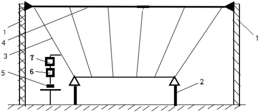
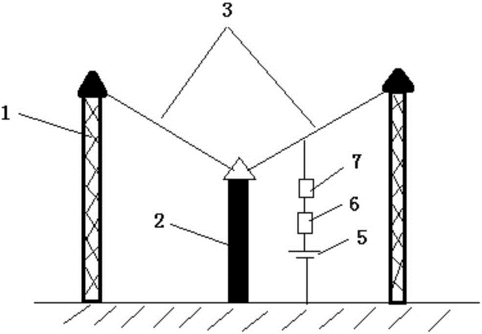
[0028] Such as Figure 1-2 As shown, a wind generating device includes potential output units A and B, each potential output unit includes two high cable support units and a low cable support unit, and the high cable support unit consists of two high supports 1 and erected The cable 4 between two high brackets 1 is composed; the low cable bracket unit is composed of two low brackets 2 and the cable 4 erected between the two low brackets; the two high cable bracket units are respectively located in the low cable bracket On both sides of the unit; between the cable 4 on the high cable support unit and the cable 4 on the low cable support unit, there are 6 launching wires 3 connected, and the total length of the launching wires 3 is 1000 meters.

[0029] The distance between the high supports is 180 meters, the height of the high supports H 0 is 35 meters, the distance D between adjacent transmitting wires 3 0 is 36 meters; the distance between two high supports is 21 meters, a...


PUM

PropertyMeasurementUnit
Lengthaaaaaaaaaa

Abstract

The invention discloses a wind creation device. The wind creation device comprises more than two electric potential output units, wherein different electric potential output units are arranged at a distance of 3,000-100,000 meters and are in potentials with opposite polarities. The device is mainly used in wind engineering, and is used for increasing precipitation and preventing forest fire.

Description


Claims


Application Information

Patent Timeline
Owner TAIYI ENVIRONMENT TECH SHANGHAI CO LTD
Why Eureka
Try Eureka