
Method and device for transmitting data across clock domains

A cross-clock domain and transmission method technology, applied in the field of cross-clock domain data transmission methods and devices, can solve the problems of inaccurate data transmission, different clock frequencies, etc.

Active Publication Date: 2019-01-04
GREE ELECTRIC APPLIANCES INC
View PDF4 Cites 0 Cited by
  • Summary
  • Abstract
  • Description
  • Claims
  • Application Information

AI Technical Summary

Problems solved by technology

[0005] Embodiments of the present invention provide a method and device for transmitting data across clock domains, so as to at least solve the technical problem of inaccurate data transmission due to the difference in clock frequency between the output circuit and the input circuit during data transmission in different clock domains

Method used


Image

  • Method and device for transmitting data across clock domains
  • Method and device for transmitting data across clock domains
  • Method and device for transmitting data across clock domains

Examples


Embodiment 1

[0023] According to an embodiment of the present invention, an embodiment of a method for transmitting data across clock domains is provided. It should be noted that the steps shown in the flowcharts of the accompanying drawings can be executed in a computer system such as a set of computer-executable instructions , and, although a logical order is shown in the flowcharts, in some cases the steps shown or described may be performed in an order different from that shown or described herein.

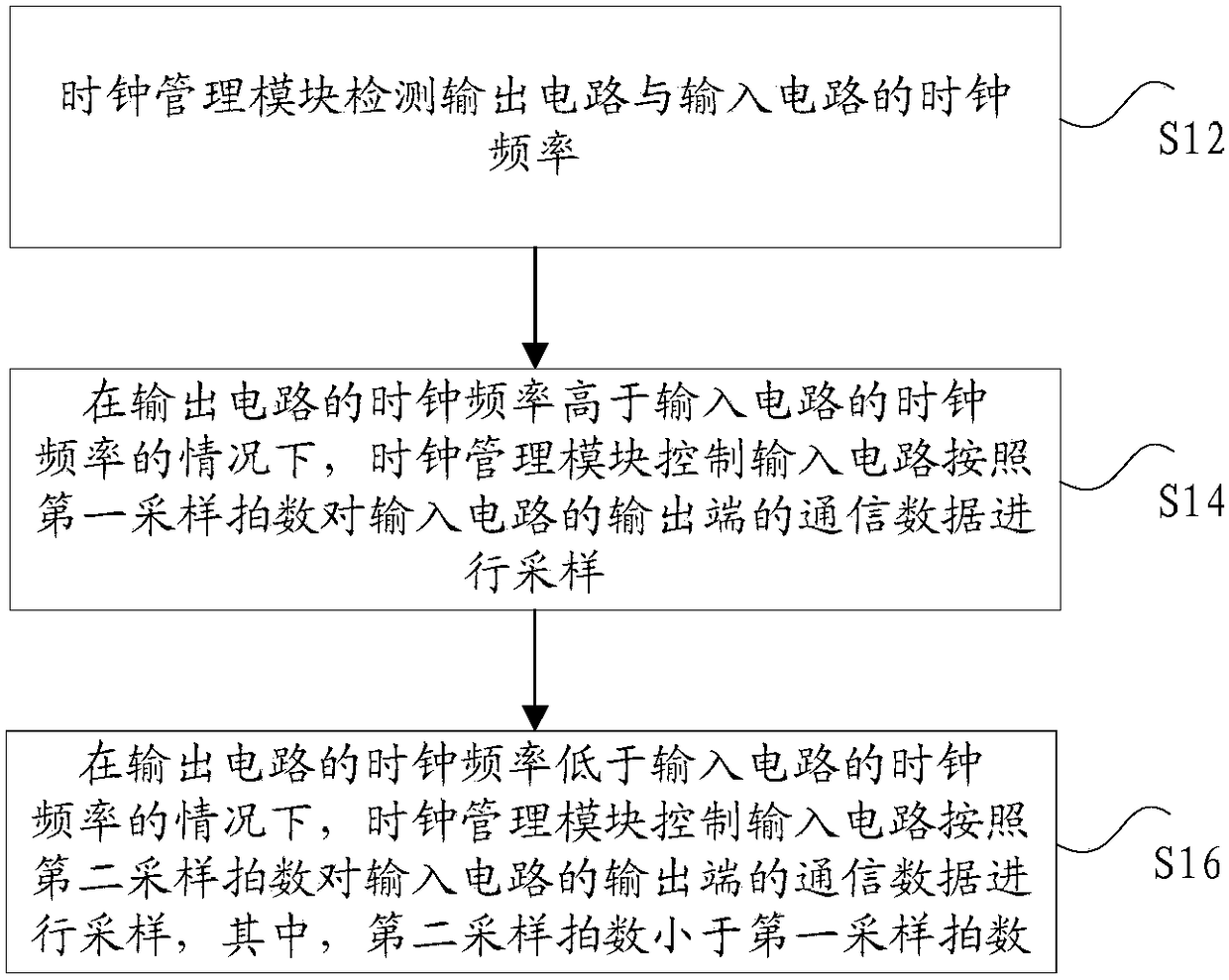
[0024] figure 1 is a method for transmitting data across clock domains according to an embodiment of the present invention, such as figure 1 As shown, the method may include:

[0025] Step S12, the clock management module detects the clock frequencies of the output circuit and the input circuit, wherein the output circuit and the input circuit are in different clock domains.

[0026] Specifically, this solution is applied to an asynchronous circuit, which may include an output circuit, a...

Embodiment 2

[0052] The present application also provides a device for transmitting data across clock domains, such as Figure 8 As shown, the above device may include: an output circuit and an input circuit in different clock domains, wherein the device may also include:

[0053] The clock management module 80 is used for detecting the clock frequency of the output circuit 82 and the input circuit 84 .

[0054] When the clock frequency of the output circuit 82 is higher than the clock frequency of the input circuit 84, the clock management module 80 is used to control the input 84 circuit to sample the communication data at the output end of the output circuit 82 according to the first sampling rate;

[0055] When the clock frequency of the output circuit is lower than the clock frequency of the input circuit, the clock management module is used to control the input circuit 84 to sample the communication data at the output end of the output circuit 82 according to the second sampling rate...


PUM


Abstract

The invention discloses a clock domain crossing data transmission method and device.The method comprises the steps that a clock management module detects the clock frequency of an output circuit and an input circuit; when the clock frequency of the output circuit is higher than that of the input circuit, the clock management module controls the input circuit to sample communication data of the output end of the input circuit according to a first sampling beat number; when the clock frequency of the output circuit is lower than that of the input circuit, the clock management module controls the input circuit to sample communication data of the output end of the input circuit according to a second sampling beat number; the second sampling beat number is smaller than the first sampling beat number.The technical problem that inaccurate data transmission is caused by difference in clock frequency of the output circuit and the input circuit during clock domain crossing data transmission of data is solved.

Description

technical field [0001] The present invention relates to the field of chips, in particular to a method and device for transmitting data across clock domains. Background technique [0002] At present, more and more mainstream chips adopt SoC (System on Chip) design, which means that a system is integrated on a chip, and this system will adopt different architectures according to the usage scenarios. Most SoCs include processors. Core, memory, internal bus, peripheral circuits and other circuit modules. With the development of the semiconductor industry, more and more circuit modules will be integrated on the chip, and when the chip is working, data must be transmitted between each circuit module. [0003] It should be noted that since each circuit module is in a different clock domain and each circuit module is in a different clock frequency, each circuit module (such as an output circuit and an input circuit) may have a risk of metastability in the circuit during data transm...

Claims


Application Information

Patent Timeline
Patent Type & Authority Patents(China)
IPC IPC(8): G06F13/20
CPCG06F13/20
Inventor 方励
Owner GREE ELECTRIC APPLIANCES INC
Learn More