A kind of fenestrated film-covered stent

A stent-graft and fenestration technology, applied in the field of medical devices, can solve the problems of hemangioma enlargement, blood vessel wall thinning, patient death, etc., and achieve the effects of less trauma, less pain, and simple operation.

Active Publication Date: 2019-07-05
谷涌泉
View PDF11 Cites 0 Cited by
  • Summary
  • Abstract
  • Description
  • Claims
  • Application Information

AI Technical Summary

Problems solved by technology

Sustained endoleak will lead to hemangioma enlargement, vessel wall thinning, and even rupture, eventually leading to death of the patient
[0005] The biggest disadvantage in the design of the existing fenestrated stent-grafts is that the operation is complicated and it is difficult to release during the operation
At present, there is no fenestrated stent graft that is easy to operate and can effectively reduce the phenomenon of "endoleakage"

Method used


Image

  • A kind of fenestrated film-covered stent
  • A kind of fenestrated film-covered stent
  • A kind of fenestrated film-covered stent

Examples


Embodiment 1

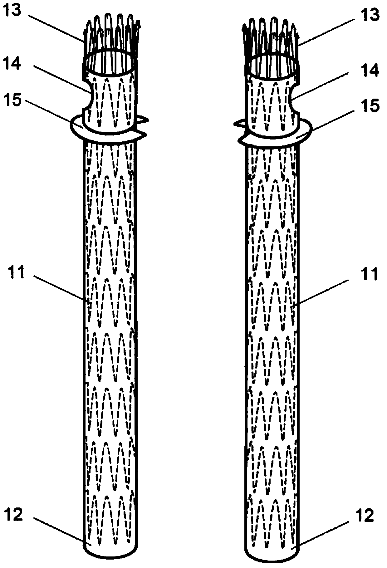
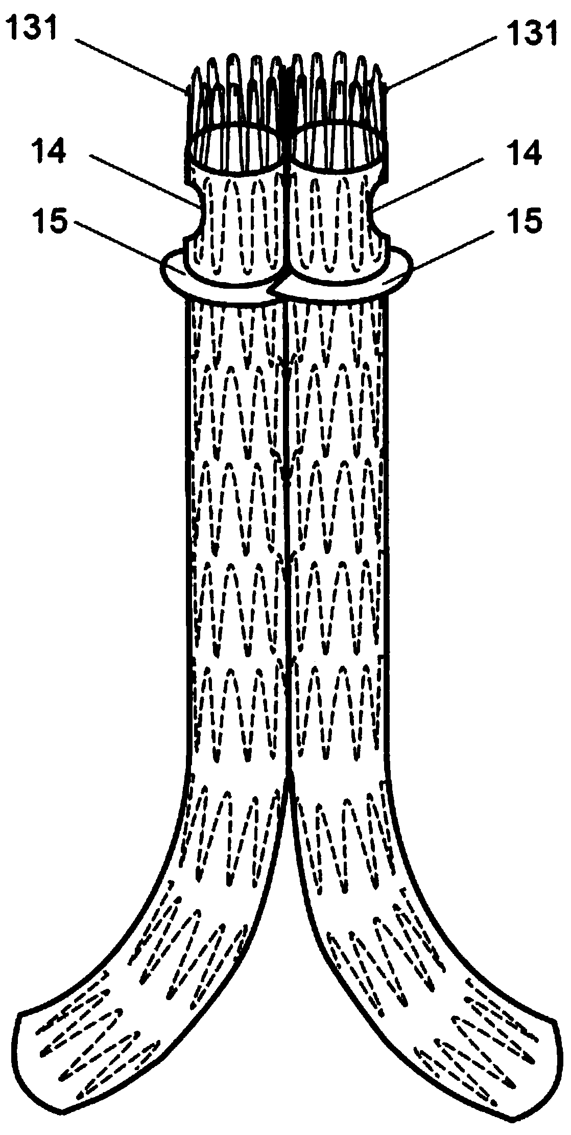
[0029] refer to figure 1 and figure 2 As shown, a fenestrated stent-graft consists of two stent units, each stent unit consists of a metal stent 11, a film 12 coated on the surface of the metal stent and a bare metal stent 13 connected to the top of the metal stent, A circular fenestration area 14 is provided at the proximal end of each stent unit, and a membrane 15 is arranged on the outer periphery of the film below the fenestration area 14, and the shape of the membrane 15 is 3 / 4 of a circle.

[0030] The diaphragm 15 is located 0.5 cm away from the lower edge of the window area 14, the thickness of the diaphragm 15 is 2 mm, and the width is 2 mm. The far end of the bracket unit is straight. The bare metal stent 13 is provided with an anti-off fixing structure 131; the coating 12 and the diaphragm 15 are made of polytetrafluoroethylene, a polymer material with good biocompatibility; the metal stents are arranged in sequence along the axial direction of the coating, and ...

Embodiment 2

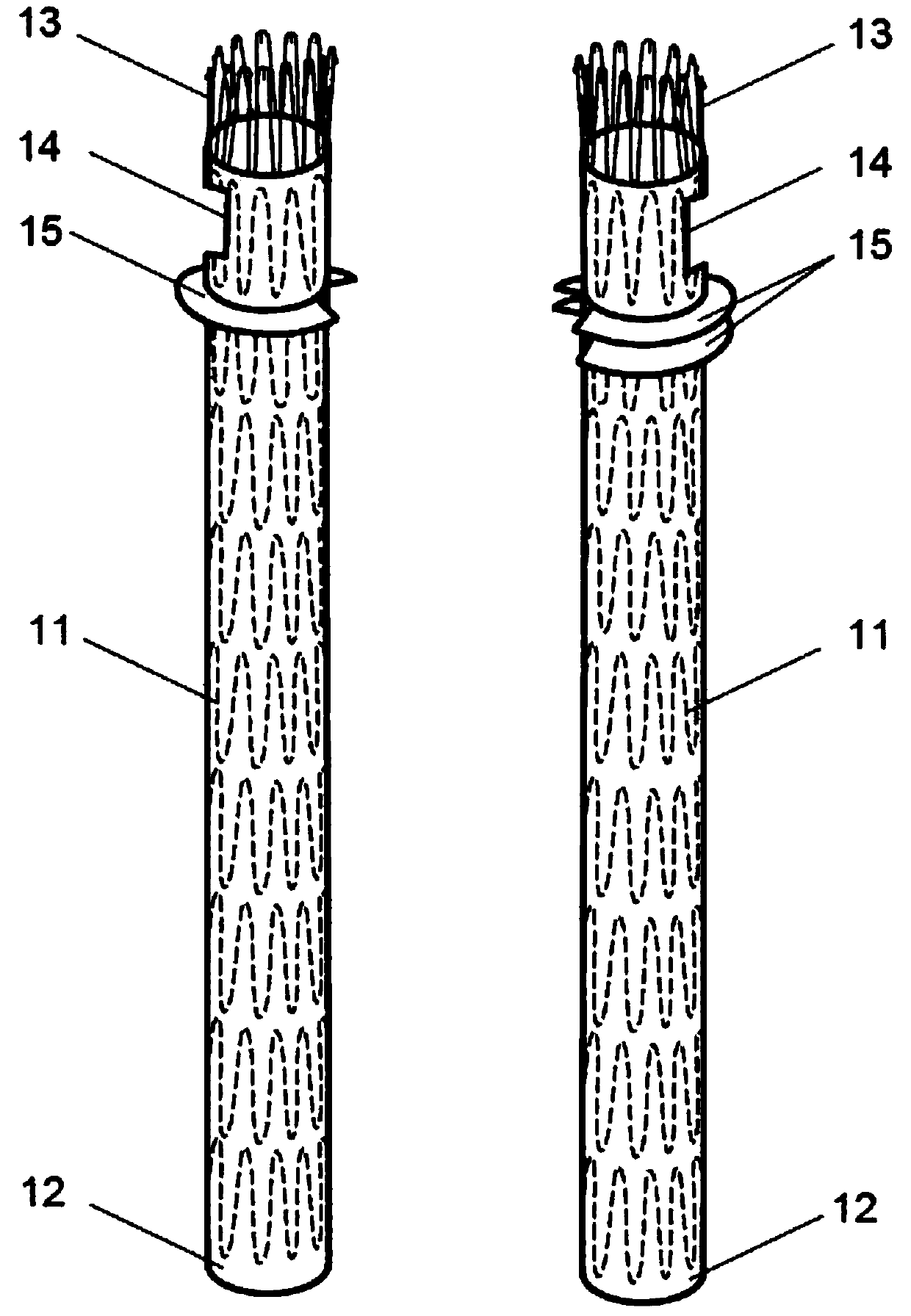
[0032] refer to image 3 and Figure 4 As shown, a fenestrated stent-graft consists of two stent units, each stent unit consists of a metal stent 11, a film 12 coated on the surface of the metal stent and a bare metal stent 13 connected to the top of the metal stent, A rectangular fenestration area 14 is provided at the proximal end of each stent unit, and a membrane 15 is arranged on the outer periphery of the film below the fenestration area 14, and the shape of the membrane 15 is 2 / 3 of a circle.

[0033] A diaphragm 15 is arranged on one side of the support unit, and the diaphragm 15 is located at a distance of 1.0 cm from the lower edge of the window area 14. The thickness of the diaphragm 15 is 2 mm, and the width is 2 mm. The far end of the bracket unit is straight.

[0034] Two diaphragms 15 are arranged on the support unit on the other side, and the diaphragm 15 above is located at 1.0 cm away from the lower edge of the window area 14. The distance between the two d...


PUM


Abstract

The invention discloses a windowing covered stent and belongs to the field of medical instruments. The windowing covered stent is composed of two support units, each support unit is composed of a metal support, a covering membrane coated on the surface of the metal support, and a metal naked support connected with the top end of the metal support, the near end of each support unit is provided with a windowing area, and at least one membrane is arranged on the periphery below each windowing area. The windowing covered stent has the advantages that the two covering membrane support units which are adjustable in position are adopted, so that the windowing covered stent is simple in surgical operation, easy to release, supportive of direct puncture, little in trauma, less prone to displacement, quite high in surgery success rate, less in suffering of patients, reliable in effect and capable of better protecting renal artery; the windowing covered stent has high wall adhesiveness with blood vessels, seam or gaps generated at part of positions between the stent and the blood vessels are avoided effectively, and internal leakage occurrence rate is lowered.

Description

technical field [0001] The invention relates to a novel fenestrated film-covered stent, which belongs to the field of medical instruments. Background technique [0002] At present, for the abdominal aortic aneurysm near the renal artery, due to the short neck of the aneurysm, it cannot be repaired with a conventional covered stent, and it is necessary to use a branch vessel stent or a window technique or a chimney technique. The operation of these three types of techniques is very complicated, so sometimes One side of the renal artery had to be sacrificed, which would lead to postoperative hypertension and, in severe cases, renal failure. [0003] The fenestrated stent-graft is to open a hole in the position where the stent-graft is directly facing the opening of important visceral arteries such as the renal artery, so that the stent-graft can anchor across important arteries, isolate the dissection gap and prevent endoleaks, while ensuring the above-mentioned vital organs ...

Claims


Application Information

Patent Timeline
Patent Type & Authority Patents(China)
IPC IPC(8): A61F2/07
CPCA61F2/07A61F2002/077
Inventor 谷涌泉
Owner 谷涌泉
Why Eureka
Try Eureka