optical imaging system

一种光学成像系统、成像面的技术,应用在光学、光学元件、仪器等方向,能够解决成像畸变率提高、周边成像质量劣化、无法满足摄影要求等问题

Active Publication Date: 2018-10-09
ABILITY OPTO ELECTRONICS TECH
View PDF7 Cites 0 Cited by
  • Summary
  • Abstract
  • Description
  • Claims
  • Application Information

AI Technical Summary

Problems solved by technology

However, the design of optical systems with large apertures often faces the situation of producing more aberrations, resulting in the deterioration of peripheral imaging quality and the difficulty of manufacturing, while the design of optical systems with wide viewing angles will face the increase of distortion rate of imaging. The advanced optical imaging system can no longer meet the requirements of more advanced photography

Method used


Image

  • optical imaging system
  • optical imaging system
  • optical imaging system

Examples


Embodiment approach

[0150] The sum of the focal lengths fp of each lens with positive refractive power in the optical imaging system is ΣPP, and the sum of the focal lengths of each lens with negative refractive power is ΣNP. An embodiment of the optical imaging system of the present invention satisfies the following conditions: <ΣPP≦200; and f1 / ΣPP≦0.85. Preferably, the following conditions may be satisfied: 0<ΣPP≦150; and 0.01≦f1 / ΣPP≦0.6. Therefore, it is helpful to control the focusing ability of the optical imaging system, and properly distribute the positive refractive power of the system to suppress the premature occurrence of significant aberrations.

[0151] The first lens may have positive refractive power, and its object side may be convex. Thus, the positive refractive power of the first lens can be properly adjusted, which helps to shorten the total length of the optical imaging system.

[0152] The second lens may have negative refractive power. Thereby, aberrations generated by t...

no. 1 example

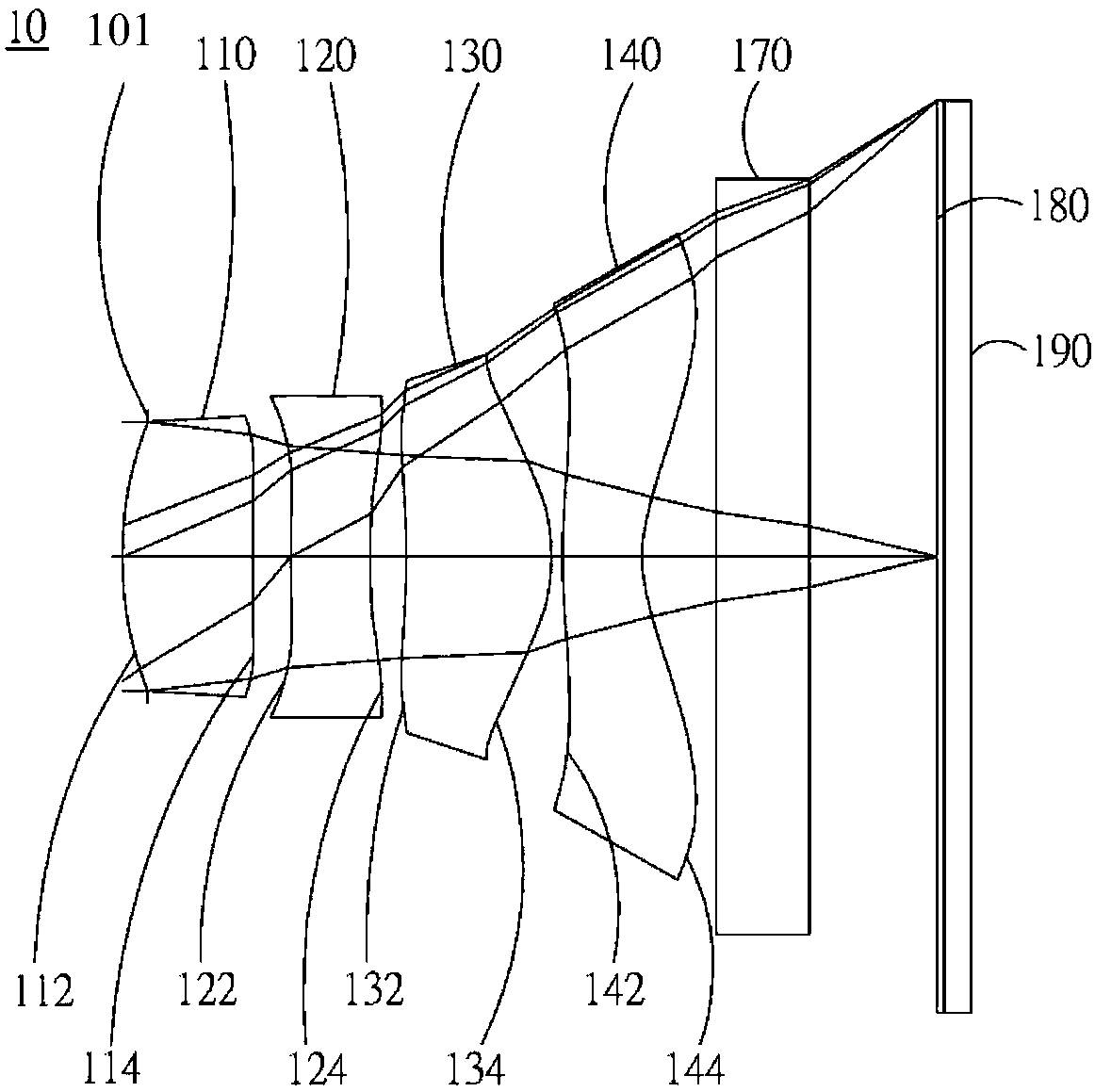
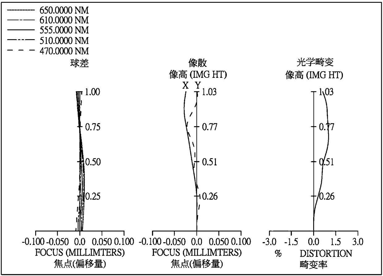
[0180] Please refer to Figure 1A and Figure 1B ,in Figure 1A A schematic diagram showing an optical imaging system according to a first embodiment of the present invention, Figure 1B From left to right are the spherical aberration, astigmatism and optical distortion curves of the optical imaging system of the first embodiment. Figure 1C It is a TV distortion curve diagram of the optical imaging system of the first embodiment. Depend on Figure 1A It can be seen that the optical imaging system 10 sequentially includes an aperture 101, a first lens 110, a second lens 120, a third lens 130, a fourth lens 140, an infrared filter 170, an imaging surface 180, and an image sensor from the object side to the image side. Element 190.

[0181]The first lens 110 has positive refractive power and is made of plastic material. The object side 112 is convex and the image side 114 is concave, both of which are aspherical. Both the object side 112 and the image side 114 have an inflecti...

no. 2 example

[0222] Please refer to Figure 2A and Figure 2B ,in Figure 2A A schematic diagram showing an optical imaging system according to a second embodiment of the present invention, Figure 2B From left to right are the spherical aberration, astigmatism and optical distortion curves of the optical imaging system of the second embodiment. Figure 2C It is a TV distortion curve diagram of the optical imaging system of the second embodiment. Depend on Figure 2A It can be seen that the optical imaging system 20 sequentially includes a first lens 210, an aperture 200, a second lens 220, a third lens 230, a fourth lens 240, an infrared filter 270, an imaging surface 280, and an image sensor from the object side to the image side. Element 290.

[0223] The first lens 210 has positive refractive power and is made of plastic material. The object side 212 is convex, and the image side 214 is convex, both of which are aspherical. The object side 212 has an inflection point.

[0224] Th...


PUM


Abstract

A four-piece optical lens for capturing image and a five-piece optical module for capturing image are disclosed. In order from an object side to an image side, the optical lens along the optical axis includes a first lens with positive refractive power; a second lens with refractive power; a third lens with refractive power; and a fourth lens with negative refractive power; and at least one of the image-side surface and object-side surface of each of the four lens elements are aspheric. The optical lens can increase aperture value and improve the imaging quality for use in compact cameras.

Description

technical field [0001] The invention relates to an optical imaging system group, more specifically, to a miniaturized optical imaging system applied to electronic products. Background technique [0002] In recent years, with the rise of portable electronic products with photography functions, the demand for optical systems has increased day by day. The photosensitive element of the general optical system is nothing more than two types of photosensitive coupling device (Charge Coupled Device; CCD) or complementary metal oxide semiconductor element (Complementary Metal-Oxide SemiconduTPor Sensor; CMOSSensor), and with the improvement of semiconductor manufacturing technology, The pixel size of the photosensitive element is reduced, and the optical system is gradually developing into the high-pixel field, so the requirements for image quality are also increasing. [0003] Traditional optical systems mounted on portable devices mostly use two-element or three-element lens struc...

Claims


Application Information

Patent Timeline
Patent Type & Authority Patents(China)
IPC IPC(8): G02B13/00G02B13/18
CPCG02B13/004G02B13/18
Inventor 刘耀维张永明
Owner ABILITY OPTO ELECTRONICS TECH
Why Eureka
Try Eureka