A Combined Air Conditioning System of Radiant Roof and Displacement Ventilation

A replacement ventilation and air-conditioning system technology, applied in the field of air-conditioning design, can solve the uncomfortable and inconvenient problems of delayed startup of the radiant roof, and achieve the effects of enhancing competitiveness, improving comfort, and reducing energy consumption

Active Publication Date: 2019-01-04
ZHEJIANG UNIV
View PDF1 Cites 0 Cited by
  • Summary
  • Abstract
  • Description
  • Claims
  • Application Information

AI Technical Summary

Problems solved by technology

[0006] The present invention provides a radiant roof and displacement ventilation combined air conditioning system. The air conditioning system combines the radiant roof and displacement ventilation, which solves the discomfort and inconvenience of delaying the startup of the traditional radiant roof / displacement ventilation combined system. problems, which further enhances the competitiveness of the combined system of radiant roof and displacement ventilation relative to the traditional convection heat exchange system, and at the same time can reduce the energy consumption of air conditioning system operation

Method used


Image

  • A Combined Air Conditioning System of Radiant Roof and Displacement Ventilation
  • A Combined Air Conditioning System of Radiant Roof and Displacement Ventilation
  • A Combined Air Conditioning System of Radiant Roof and Displacement Ventilation

Examples


Embodiment Construction

[0037] The present invention will be described in further detail below in conjunction with the accompanying drawings.

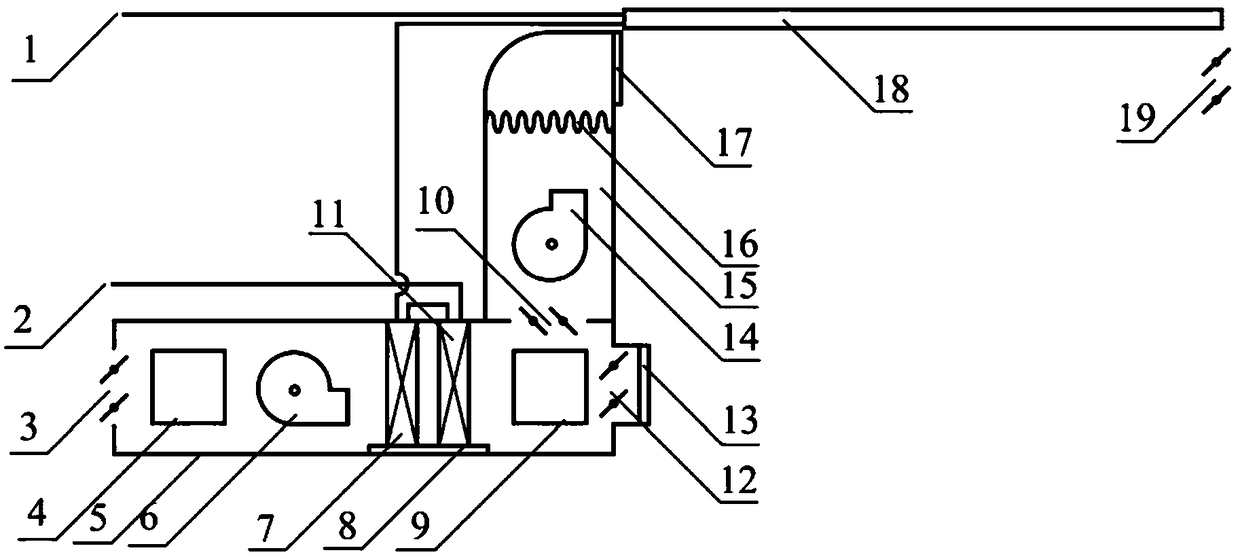
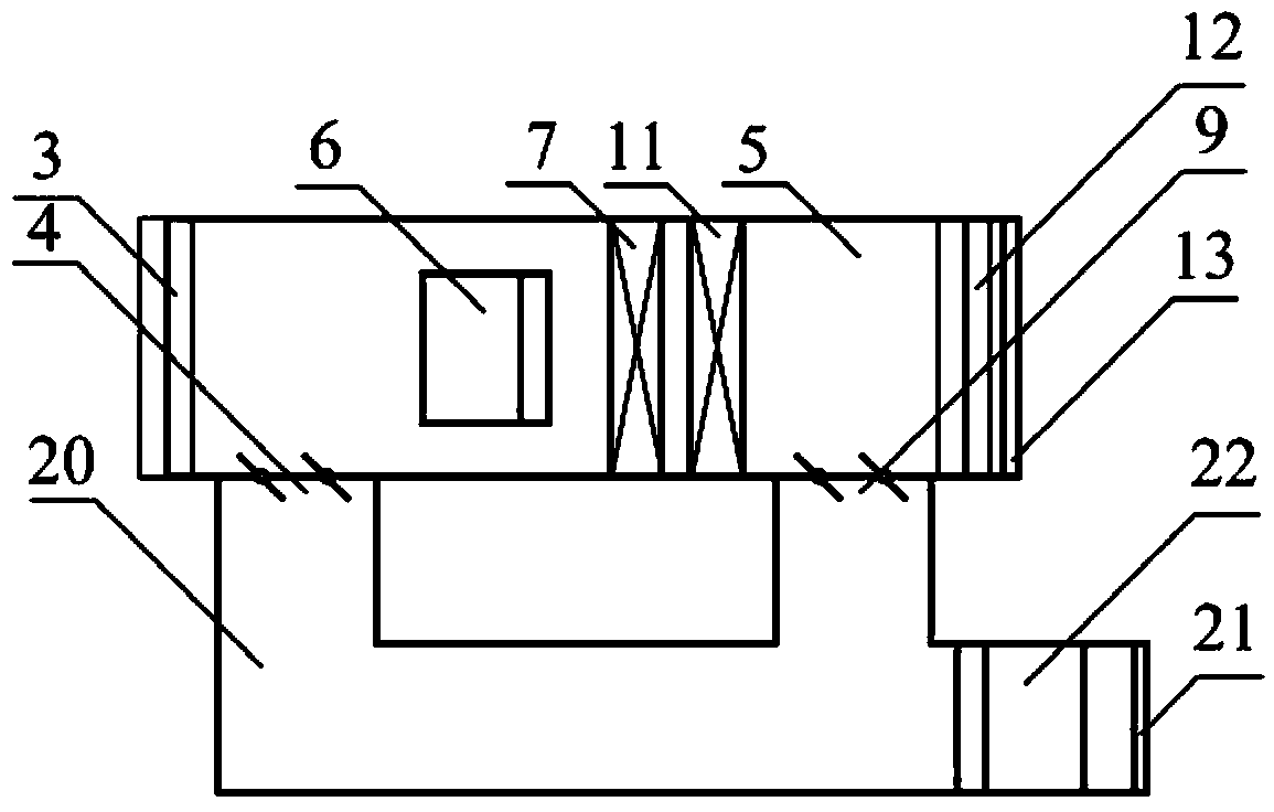
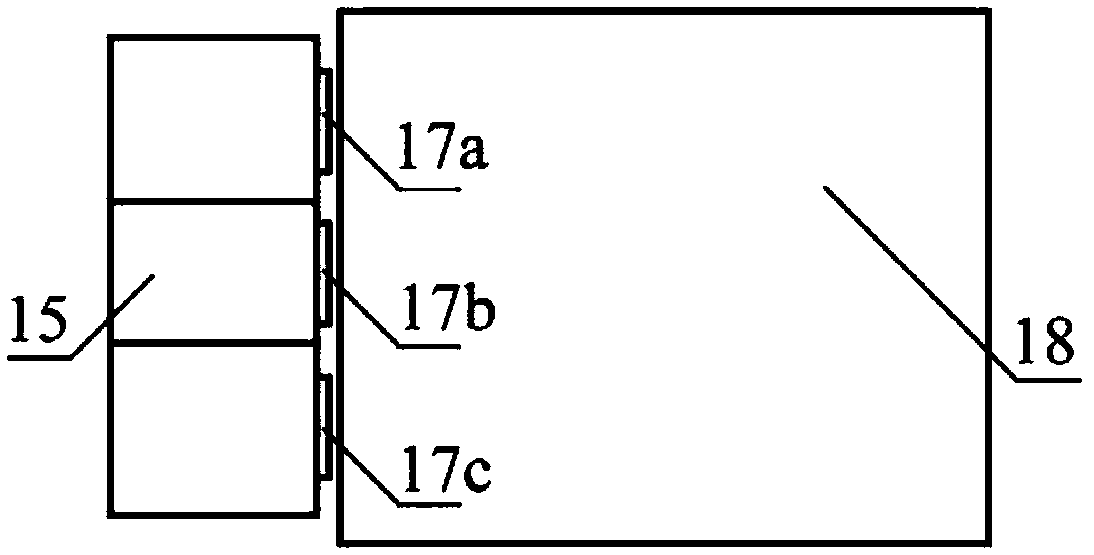
[0038] Such as figure 1 with figure 2 As shown, the present invention includes: an air treatment box 5 , a vertical air supply duct 15 , a radiation ceiling 18 and a return air duct 20 . The vertical air supply pipe 15 is located on the upper side of the indoor end of the air treatment box 5 and is connected with the air treatment box 5 through the vertical air supply valve 10 . The radiant ceiling 18 is installed under the ceiling in front of the upper air supply diffuser 17 . The air return pipe 20 is located at the side of the air treatment box 5 and is connected to the air treatment box 5 through the primary air return valve 4 and the secondary air return valve 9 .

[0039] The air treatment box 5 includes: fresh air valve 3, primary return air valve 4, first fan 6, first surface heat exchanger 7, second surface heat exchanger 11, condensation pan 8, ...


PUM


Abstract

The invention discloses an air conditioning system with combination of a radiation top plate and displacement ventilation. The air conditioning system comprises a displacement ventilation unit with an air processing tank, the radiation top plate and a vertical air supply tube formed above the displacement ventilation unit, wherein an air inlet of the vertical air supply tube is connected with the air processing tank; and an air outlet of the vertical air supply tube is arranged close to the radiation top plate, and is used for sending an air flow after being cooled to the side of the lower surface of the radiation top plate. According to the air conditioning system with combination of the radiation top plate and displacement ventilation, in the starting mode, a low-temperature dry air flow flows out from an upper part air supply diffuser so as to form a protective layer below the radiation top plate, so that the radiation top plate can be prevented from dewing, and the temperature of a room can be rapidly lowered; and in a steady mode, after a displacement ventilation air flow and secondary return air are mixed, mixed air flows out from a lower part air supply diffuser, and a low-temperature clean air layer can be formed at the lower part of the room. The air conditioning system with combination of the radiation top plate and displacement ventilation can solve the problems that when the traditional system with combination of the radiation top plate and displacement ventilation starts, the comfort degree cannot be ensured, and the starting time of the radiation top plate is long and in addition, has the characteristic of low energy consumption.

Description

technical field [0001] The invention belongs to the technical field of air-conditioning design, in particular to an air-conditioning system combined with a radiant roof and displacement ventilation. Background technique [0002] The radiant roof is a new type of air-conditioning terminal, which has the advantages of no noise, low energy consumption, and high comfort. But it also has a key problem that needs to be solved when it is cooling: when the temperature of the radiant roof is lower than the dew point temperature of the indoor air, the radiant roof has the risk of condensation. In use, the temperature of the radiant roof should be controlled to be higher than the dew point temperature of the indoor air, so the radiant roof can only handle the sensible heat load and not the latent heat load. Therefore, the combination of radiant roof and displacement ventilation is usually used abroad. The displacement ventilation system sends air directly to the user area in the lowe...

Claims


Application Information

Patent Timeline
Patent Type & Authority Patents(China)
IPC IPC(8): F24F5/00F24F3/06F24F3/14F24F7/007F24F13/28F24F13/00F24F13/30F24F13/22F24F12/00
CPCF24F3/06F24F3/14F24F5/0089F24F7/007F24F12/00F24F13/00F24F13/222F24F13/28F24F13/30F24F2003/144
Inventor 曾昭赟程梦婕王勤王旻珑廖伟涵齐裕
Owner ZHEJIANG UNIV
Why Eureka
Try Eureka