Order-variable permanent magnet rheological damper

A damper and permanent magnet technology, applied in the field of step-change permanent magnet rheological dampers, can solve the problems of high system design cost, low collection energy, and limited application environment, and achieve high application stability, low cost, and structural design simple effect

Inactive Publication Date: 2016-10-12
BEIJING JIAOTONG UNIV
View PDF6 Cites 7 Cited by
  • Summary
  • Abstract
  • Description
  • Claims
  • Application Information

AI Technical Summary

Problems solved by technology

With the wide application of magnetorheological dampers, the application of magnetorheological dampers is limited to some extent in some vibration applications where the power supply cannot be reached or the power supply is inconvenient to replace.
For this reason, in recent years, a class of self-powered magnetorheological dampers has emerged, which mainly uses energy harvesting devices that convert external mechanical vibration energy into electrical energy to replace the power supply to meet the electrical energy requirements of magnetorheological dampers Due to the relatively low harvesting energy of energy magnetorheological damper system, the application environment is limited, and the system stability is relatively low
[0004] In addition, in addition to the power supply, the external equipment required by the magnetorheological damper also needs related equipment such as sensors and controllers. The sensors test the structural response, and the controller calculates the control commands. The entire vibration control system becomes relatively complex, and the system stability is relatively low, and at the same time, the system design cost is relatively high

Method used


Image

  • Order-variable permanent magnet rheological damper
  • Order-variable permanent magnet rheological damper

Examples


Embodiment Construction

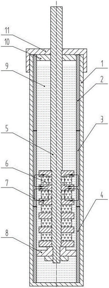
[0013] figure 1 It is a schematic diagram of the structure of the present invention. The present invention is a step-change permanent magnet rheological damper, comprising an outer cylinder 1, an inner cylinder 2, an inner cylinder 2 3, an inner cylinder 3 4, a piston rod 5, A number of permanent magnets 6, a number of magnetic blocks 7, a guide device 8, a magneto-rheological fluid 9, a sealing ring 10, and an end cover 11. The outer cylinder 1, the inner cylinder 1 2 and the inner cylinder 3 4 are all made of aluminum alloy, the inner cylinder 2 3 is electric pure iron DT4, the inner cylinder 1 2, the inner cylinder 2 3 and the inner cylinder 3 4 Quantitative magnetorheological fluid 9 is distributed inside. The shaft diameter at one end of the piston rod 5 is small, and several magnetic blocks 7 with inner holes and several permanent magnets 6 are sequentially installed on it to form a piston structure. Each adjacent permanent magnet 6 adopts the magnetic pole of the same ...


PUM


Abstract

The invention relates to an order-variable permanent magnet rheological damper and belongs to the field of mechanical vibration engineering. The order-variable permanent magnet rheological damper is a non-power-supply damping vibration absorber. The on-off states of a permanent magnet circuit are controlled by changing the magnetic permeability and the axial effective length of an inner cylinder tube, so that the output damping force, changing along with the piston stroke, of the permanent magnet rheological damper is adjusted, order-variable output of coulomb damping force is achieved, preset damping force is obtained, and effective shock absorption is conducted. An inner cylinder tube section of the order-variable permanent magnet rheological damper is formed by fixedly connecting one section of magnetic-permeability material cylinder tube and two sections of non-magnetic-permeability material cylinder tubes, and a permanent magnet structure piston is a multilevel electromagnetic circuit. The permanent magnet rheological damper is free of energy consumption, simple in structural design and high in stability and has other shock absorption properties.

Description

technical field [0001] The invention relates to a permanent magnet rheological vibration control technology, in particular to a stepped permanent magnet rheological damper. Background technique [0002] The magnetorheological damper is a most promising semi-active control device developed by using the rheological characteristics of magnetorheological fluid. It has both the reliability of passive control and the adaptability of active control, and compared with active control Low energy consumption, wide dynamic range, fast response, low energy consumption, simple mechanical structure, strong environmental robustness, easy to combine with microcomputer control and other outstanding advantages. Magnetorheological dampers have been widely used in vibration control systems, such as vehicle suspension systems, aircraft landing gear systems, building earthquake protection systems, cable-stayed bridge protection systems, medical rehabilitation systems and other fields. [0003] Th...

Claims


Application Information

Patent Timeline
Patent Type & Authority Applications(China)
IPC IPC(8): F16F9/53F16F9/48
CPCF16F9/48F16F9/535F16F2224/045
Inventor 王四棋李德才张天奇
Owner BEIJING JIAOTONG UNIV
Why Eureka
Try Eureka