Transient measurement method for barefoot well formation resistivity

A technology of formation resistivity and measurement method, which is applied in boreholes/well components, earthwork drilling and production, etc., can solve the problems of single excitation frequency, shallow radial detection depth, and simple way of carrying formation resistivity information by original signals

Inactive Publication Date: 2017-01-11
中石化石油工程技术服务有限公司 +1
View PDF5 Cites 21 Cited by
  • Summary
  • Abstract
  • Description
  • Claims
  • Application Information

AI Technical Summary

Problems solved by technology

[0003] The patent of this invention aims at the problems of single excitation frequency, shallow radial detection depth and s

Method used


Image

  • Transient measurement method for barefoot well formation resistivity
  • Transient measurement method for barefoot well formation resistivity
  • Transient measurement method for barefoot well formation resistivity

Examples


Embodiment 1

[0025] see Figure 4 . Signal transmission 1 generates transmission information, signal reception 2 obtains test signals, and passes through calibration system 3 to obtain a series of calibration coefficients 6 and 7. Among them, the calibration system is further divided into the Fourier transformation calibration method 5 and the calibration method 4 where the quadratic field takes the extreme value. After the calibration coefficient is obtained, the calibration of the instrument is completed, and the formation resistivity test can be carried out.

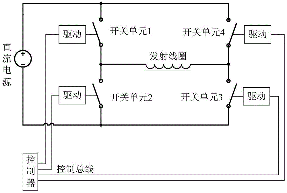
[0026] Such as figure 1 As shown, the transmitting circuit uses four high-power tubes, and the on-off of the power tubes is controlled by the control circuit and the driving circuit, so that the current of the transmitting coil flows in the forward and reverse directions, so that the forward and reverse signals are transmitted. The transmitting power adopts direct current, and the transmitting coil has current passing through t...

Embodiment 2

[0036] The transmitting and receiving coils of the induction logging tool are coaxially installed, and the inside of the coil is filled with magnetic material, and placed in the open hole.

[0037] The transmitting power supply is a stable direct current, which is controlled by a high-power tube in the full bridge circuit to generate a low-frequency bipolar rectangular waveform on the transmitting coil, with a frequency range of 0.1 to 100 Hz. Reasonably configure the voltage value of the transmitting power supply and the resistance value of the transmitting coil, so that the intensity of the passing DC current is relatively large, and high-power transmission is realized.

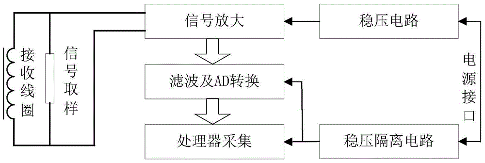
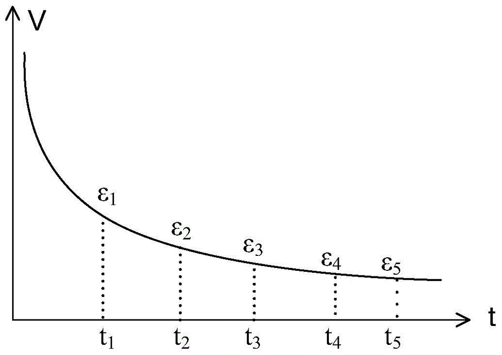
[0038] The received voltage is composed of two parts, one is the direct coupled primary field, which has nothing to do with the formation resistivity, and the other is the secondary field, which is directly related to the formation resistivity. The primary field is removed by the calibration method, leaving...


PUM

PropertyMeasurementUnit
Pressure valueaaaaaaaaaa

Abstract

The invention relates to a transient measurement method for the barefoot well formation resistivity. An emitting coil and a receiving coil of an induction logging instrument are coaxially placed in a formation; the emitting coil is controlled by a high power transistor in a full bridge converter, high-power and low-frequency bipolar rectangular waveforms are generated on the emitting coil, trigger signals trigger a receiving circuit at the moments of current disconnection and current connection, and transient voltage response waveforms inducted by the receiving coil are recorded; scale operation is conducted on transient response waveforms received by the tested formation and a set of received signals of a standard formation, and only a secondary field for reflecting the resistivity difference ratio of the tested formation is left; and the resistivity of the tested formation is obtained from response waveforms of the secondary field. According to the transient measurement method, the application range of a transient electromagnetic method to logging is widened, the method can be complementary to a common induction logging method, and obtained resistivity logging data can be used for formation evaluation and reservoir stratum division in the logging interpreting process, and also can be used for calculating the porosity, the saturability, the permeability and other parameters of reservoir stratums.

Description

technical field [0001] The invention relates to a transient measurement method for open-hole formation resistivity in the field of petroleum logging engineering methods, in particular to a transient measurement method for effective measurement of formation resistivity parameters at different radial depths and relatively deep radial detection depth. state logging method. Background technique [0002] In the process of petroleum exploration and development, in order to evaluate the oil saturation of the formation, it is necessary to measure the formation resistivity effectively. The current prior art adopts methods such as induction, double induction, array induction and double lateral direction, and the excitation waveforms are sine wave (or square wave) and direct current respectively. The excitation frequency is single, the excitation power is relatively small, the radial detection depth is limited, and the original signal carries formation resistivity information in a sin...

Claims


Application Information

Patent Timeline
IPC IPC(8): E21B49/00
Inventor 臧德福沈建国张付明张守伟
Owner 中石化石油工程技术服务有限公司
Why Eureka
Try Eureka