An air duct cross fitting

A technology of intersecting pipes and air ducts, which is applied in the field of civil engineering HVAC, and can solve the problems of intersecting air ducts occupying the vertical height space of buildings

Active Publication Date: 2022-03-15
YANTAI UNIV
View PDF7 Cites 0 Cited by
  • Summary
  • Abstract
  • Description
  • Claims
  • Application Information

AI Technical Summary

Problems solved by technology

[0004] In order to solve the problem that the local resistance of the crossing of air pipes in the new exhaust and ventilation system of the building increases and the vertical space of the building is occupied, especially in places such as offices and hotel buildings where fresh air ventilators are used, the present invention provides a The air duct cross fittings of the wind ventilation system, which can minimize the airflow loss in the cross ducts, and also solve the problem that the cross ducts of the new building exhaust and ventilation system occupy the vertical height space of the building

Method used


Image

  • An air duct cross fitting
  • An air duct cross fitting
  • An air duct cross fitting

Examples


Embodiment 1

[0031] Example 1 A wind tube cross pipe for a new exhaust ventilation system, which is designed in accordance with the actual application of the engineering, and verifies that the relevant parameters and efficacy data are verified by the application of the specific HVAC. .

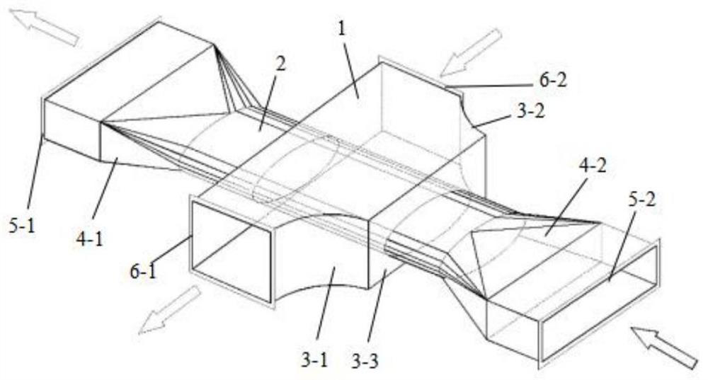
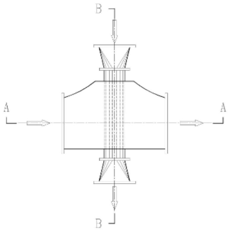
[0032] Such as Figure 1-5 As shown, a cross section of the outer tube of the main tube expansion 1, the outer tube of the air tube 2, and the main air tube expansion 1 is in a rectangle. On one side of the expansion, the expansion portion is composed of the expansion portion 3-1 and the expanded portion 2 3-2, and the recession bonding portion 3-3 is made, and the other side is not expanded.

[0033]The tubular members in this embodiment include the main wind tube expansion 1, the air tube 2, the variable tube one 4-1 and the vials 2 4-2, the air outlet flange 1 5-1 and the air-pin flange 2 5-2 , Wind flange three 6-1 and air-pin flange 4 6-2, main wind pipe expansion 1 ends connected to the airport flange thr...


PUM


Abstract

The invention provides an air duct cross fitting used in a new exhaust ventilation system. The cross fitting can minimize the airflow loss in the cross duct, and at the same time solves the problem of intersecting air duct occupation in the new exhaust ventilation system of a building. The problem of building vertical height space.

Description

Technical field [0001] The present invention relates to a wind tube cross pipe, and specifically, a wind tube cross pipe for a new exhaust system, belonging to the technical field of civil engineering HVAC. Background technique [0002] In the building ventilation ventilation system, there is often a problem of vertical cross-stroke of new wind tubes and exhaust wind tubes. The usual way is to arrange the new wind tubes and exhaust pipes in the vertical direction, since the duct size is relatively large. The cross of the wind tube will occupy a large vertical height, usually take a high level of highlighting to ensure that the level is high, thereby causing an increase in the height of at least 200 mm per layer, making the cost of civil construction. [0003] Especially in some civil buildings such as high-level office, hotels, new wind and drainage often use new wind ventilation to recycle drain energy, new wind main wind pipes and exhaust main wind tubes are placed in parallel ...

Claims


Application Information

Patent Timeline
Patent Type & Authority Patents(China)
IPC IPC(8): F24F13/02F24F7/007
CPCF24F7/007F24F13/02F24F13/0209F24F13/0245
Inventor 张玲玲
Owner YANTAI UNIV
Why Eureka
Try Eureka