Rotary compressor and refrigeration cycle device
A rotary compressor, compression chamber technology, used in rotary piston machinery, rotary piston pumps, rotary piston/oscillating piston pump components, etc.
- Summary
- Abstract
- Description
- Claims
- Application Information
AI Technical Summary
Problems solved by technology
Method used
Image

Examples
no. 1 Embodiment approach
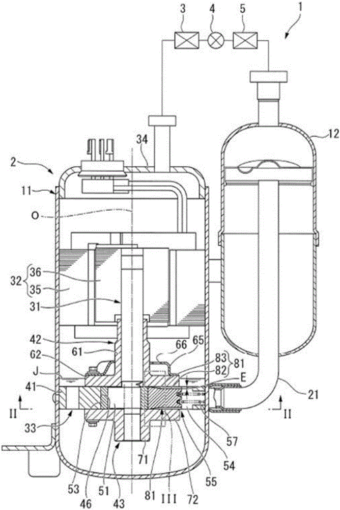
[0076] First, the refrigeration cycle apparatus 1 will be briefly described. figure 1 It is a schematic configuration diagram of the refrigeration cycle apparatus 1 including a cross-sectional view of the rotary compressor 2 in the first embodiment.
[0077] Such as figure 1 As shown, the refrigeration cycle apparatus 1 of this embodiment includes a rotary compressor 2, a radiator 3 connected to the rotary compressor 2, an expansion device 4 connected to the radiator 3, and a rotary compressor connected to the expansion device 4. Evaporator 5 of machine 2.
[0078] The rotary compressor 2 is a so-called rotary compressor. The rotary compressor 2 compresses the low-pressure gas refrigerant introduced into the inside to become a high-temperature and high-pressure gas refrigerant. In addition, the specific structure of the rotary compressor 2 will be mentioned later.
[0079] The radiator 3 dissipates heat from the high-temperature and high-pressure gas refrigerant sent from ...
no. 2 Embodiment approach
[0150] Figure 7 It is a plan view of the blade 155 in 2nd Embodiment. In addition, in the following description, the same code|symbol is attached|subjected to the structure similar to the said 1st Embodiment, and description is abbreviate|omitted.
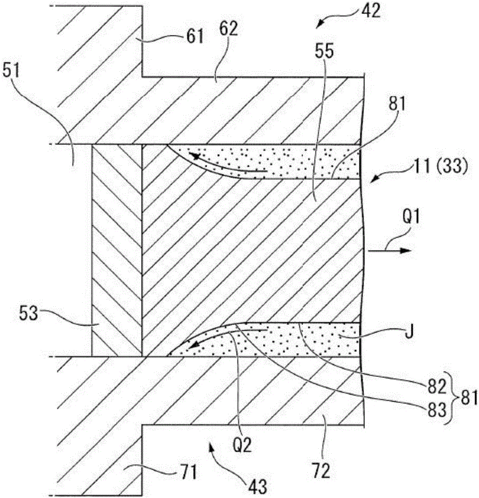
[0151] Figure 7 In the illustrated blade 155 , the groove width H of the oil supply groove 181 becomes narrower from the outer side toward the inner side in the radial direction. However, the oil supply groove 181 has only to narrow the groove width H at least at the inner end in the radial direction. That is, the oil supply groove 181 may have the same groove width H at the outer end in the radial direction, and may have a narrower groove width H at the inner end in the radial direction. and, Figure 7 In the illustrated example, the oil supply groove 181 is formed in a trapezoidal shape when viewed from the axial direction, but is not limited thereto, and may be formed in a triangular shape (a shape that becomes sharper tow...
no. 3 Embodiment approach
[0158] Figure 8 It is a plan view of the blade 255 in 3rd Embodiment. In addition, in the following description, the same code|symbol is attached|subjected to the structure similar to the said 2nd Embodiment, and description is abbreviate|omitted.
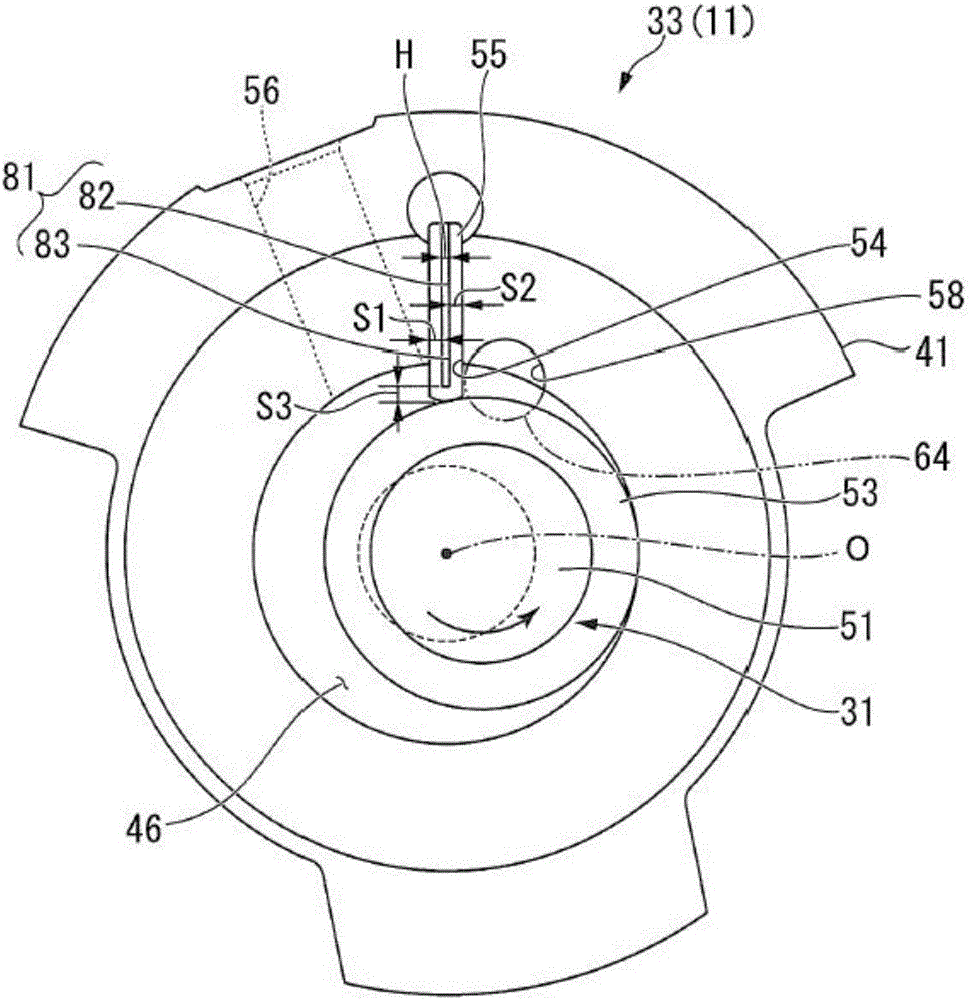
[0159] Figure 8 In the vane 255 shown, the center T1 of the oil supply groove 181 is offset to the compression chamber with respect to the center T2 of the vane 255 in the vane width direction. Therefore, the sealing width S2 of the portion of the sealing surface located closer to the compression chamber relative to the oil supply groove 181 is narrower than the sealing width S1 of the portion located closer to the suction chamber relative to the oil supply groove 181 .
[0160] According to this configuration, the sealing width S1 of the portion of the sealing surface that is located closer to the suction chamber with respect to the oil supply groove 181 can be ensured, so that leakage of the refrigerant from the compression c...
PUM
| Property | Measurement | Unit |
|---|---|---|
| Dynamic viscosity | aaaaa | aaaaa |
| Dynamic viscosity | aaaaa | aaaaa |
Abstract
Description
Claims
Application Information
 - R&D Engineer
- R&D Manager
- IP Professional
- Industry Leading Data Capabilities
- Powerful AI technology
- Patent DNA Extraction
Browse by: Latest US Patents, China's latest patents, Technical Efficacy Thesaurus, Application Domain, Technology Topic.
© 2024 PatSnap. All rights reserved.Legal|Privacy policy|Modern Slavery Act Transparency Statement|Sitemap