Natural gas liquefying system for carbon dioxide precooling double-stage nitrogen expansion

A carbon dioxide and natural gas technology, applied in the field of natural gas liquefaction, can solve the problems of reduced economy, increased wall thickness, unfavorable production, etc., and achieve the effects of improving sea adaptability, avoiding the use of propane, and improving process flexibility

Active Publication Date: 2017-02-22
CHINA HUANQIU CONTRACTING & ENG CO LTD
View PDF10 Cites 13 Cited by
  • Summary
  • Abstract
  • Description
  • Claims
  • Application Information

AI Technical Summary

Problems solved by technology

In the prior art, the pressure of the high-temperature nitrogen cycle and the low-temperature nitrogen cycle are the same, and the process design cannot adjust the heat transfer temperature difference in different temperature zones, and the adjustability is poor, which reduces the environmental adaptability and feed gas adaptability of the FLNG device, which is not conducive to stable and efficient production
[0007] After being pressurized by the expander booster and compressor, the nitrogen pressure is as high as 5MPa or more, the pressure level of equipment and pipelines is high, the wall thickness increases, and the weight of process equipment increases, resulting in an increase in the load of supporting structures such as pipe racks, and damage The strength of the hull structure puts forward higher requirements, and the cost of the upper process module and the hull rises sharply, which increases the investment and reduces the economy of the floating natural gas liquefaction device
[0008] In summary, the existing floating natural gas liquefaction technology has the disadvantages of low safety, poor adjustability, high energy consumption, and poor economy

Method used


Image

  • Natural gas liquefying system for carbon dioxide precooling double-stage nitrogen expansion
  • Natural gas liquefying system for carbon dioxide precooling double-stage nitrogen expansion
  • Natural gas liquefying system for carbon dioxide precooling double-stage nitrogen expansion

Examples


Embodiment Construction

[0035] The following will clearly and completely describe the technical solutions in the embodiments of the present invention with reference to the accompanying drawings in the embodiments of the present invention. Obviously, the described embodiments are only some, not all, embodiments of the present invention. Based on the embodiments of the present invention, all other embodiments obtained by persons of ordinary skill in the art without making creative efforts belong to the protection scope of the present invention.

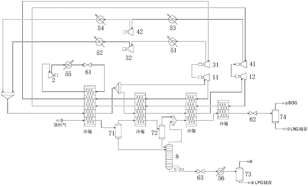
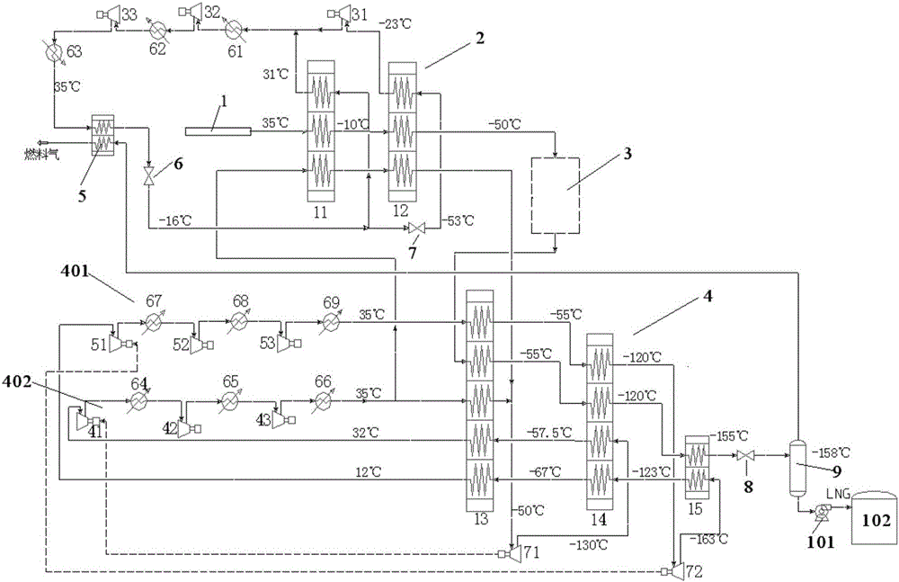
[0036] figure 2 It is a schematic diagram of a natural gas liquefaction system for carbon dioxide pre-cooling two-stage nitrogen expansion in an embodiment of the present invention. As shown in the figure, the carbon dioxide pre-cooling two-stage nitrogen expansion natural gas liquefaction system provided by the present invention includes: natural gas delivery pipe 1, carbon dioxide pre-cooling Cold cycle device 2, heavy hydrocarbon removal device 3, two-stag...


PUM


Abstract

The invention discloses a natural gas liquefying system for carbon dioxide precooling double-stage nitrogen expansion. The natural gas liquefying system comprises a natural gas conveying pipe, a carbon dioxide precooling circulating device, a heavy hydrocarbon removing device, a double-stage nitrogen cooling circulating device, a BOG heat exchanger, a first throttling valve, a second throttling valve, a LNG throttling valve, a gas-liquid separation device, a LNG pump and a LNG tank. The natural gas liquefying system realizes precooling through carbon dioxide and deep cooling through nitrogen, optimally designs the technological process of a carbon dioxide precooling double-stage nitrogen expansion liquefying system, improves the process flexibility, reduces the energy consumption of the liquefying system, improves the safety, and can realize stable, efficient and continuous production demands of offshore liquefied natural gas under the conditions of different sea areas and different gas properties.

Description

technical field [0001] The invention relates to the field of natural gas liquefaction, in particular to a carbon dioxide precooling two-stage nitrogen expansion natural gas liquefaction system. Background technique [0002] Natural gas resources are widely distributed on land and oceans around the world. From land to ocean is an inevitable trend of oil and gas exploration and development in the world. FLNG (Floating Liquefied Natural Gas) is a new type of offshore device proposed by the marine engineering community in recent years, which integrates the production, storage and loading and unloading of liquefied natural gas. It has low investment costs, short construction periods, and low development risks for the exploitation of offshore gas fields. Ease of migration and other features. [0003] Unfavorable factors such as typhoons, waves, and space constraints need to be considered in offshore operations, making the technical difficulty of floating liquefaction process high...

Claims


Application Information

Patent Timeline
Patent Type & Authority Applications(China)
IPC IPC(8): F25J1/02
CPCF25J1/0022F25J1/0205F25J1/0281F25J1/0035F25J1/005F25J1/0052F25J1/0072F25J1/0095F25J1/0207F25J1/0262F25J1/0267F25J1/0288F25J2220/62F25J5/002
Inventor 季鹏陈振中白改玲王红安小霞
Owner CHINA HUANQIU CONTRACTING & ENG CO LTD
Why Eureka
Try Eureka