Low-profile lens antenna based on reflective array feed

A technology of lens antennas and reflectarrays, which is applied in the direction of antennas and electrical components, can solve the problems of limiting the application range of folded reflectarrays, the inability to achieve dual polarization or circular polarization, and increasing processing and production costs, achieving multiple degrees of design freedom , short preparation cycle and light weight

Active Publication Date: 2017-02-22
UNIV OF ELECTRONICS SCI & TECH OF CHINA
View PDF5 Cites 16 Cited by
  • Summary
  • Abstract
  • Description
  • Claims
  • Application Information

AI Technical Summary

Problems solved by technology

However, since the polarized grid can only pass through electromagnetic waves whose polarization direction is parallel to it, dual polarization or circular polarization cannot be achieved, which limits the application range of the folded reflectarray.
A.Abbaspour-Tamijani et al. disclose a lens antenna based on phased array feeding (A.Abbaspour-Tamijani, L.Zhang, G.Pan, H.K.Pan, and H.Alavi, "Lens-enhanced phased array antenna system for highdirectivity beam-steering,” in Proc.IEEE Int.Symp.on Antennas and Propagation (APSURSI), Jul.2011, pp.3275–3278), but the use of phased array feed will increase the Loss and increased processing and production costs

Method used


Image

  • Low-profile lens antenna based on reflective array feed
  • Low-profile lens antenna based on reflective array feed
  • Low-profile lens antenna based on reflective array feed

Examples


Embodiment 1

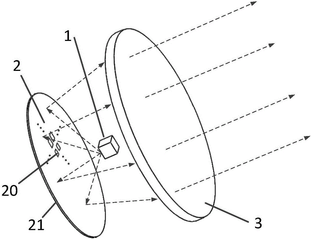
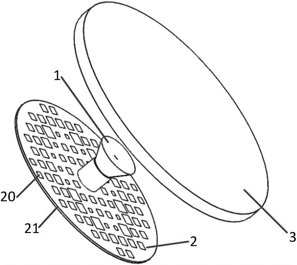
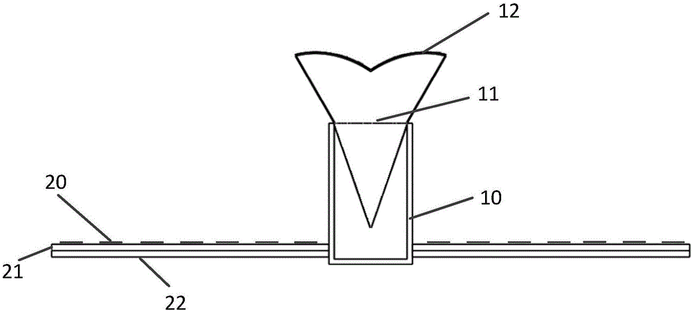
[0024] In this example, the ring-focus Cassegrain reflector array is used to feed the lens. The overall structure is as follows: figure 2 As shown, it includes a ring-focus feed 1 supported by a dielectric block 11 , a plate reflection array 2 printed with a microstrip patch unit 20 located at the bottom of the ring-focus feed 1 , and a lens 3 located above the ring-focus feed 1 . The schematic diagram of the structure of the specific ring-focus feed and reflector array is as follows: image 3 As shown, the ring-focus feed source is composed of a C120 standard circular waveguide 10 with a radius of 8.737mm, a dielectric block 11 embedded in the standard circular waveguide, and a metal sub-reflector 12 coated on the top of the dielectric block 11. The dielectric block 11 adopts the dielectric constant The polytetrafluoroethylene material of 2.2 is used for impedance matching and supporting the metal sub-reflecting surface 12 . The flat reflector array 2 is composed of 92 rect...

Embodiment 2

[0027] The reflectarray-fed lens antenna in this example uses a common feed horn to feed the reflectarray. The overall structure is as follows: Figure 5 As shown, the primary horn is a conical horn 1 supported by four support rods 13 , the reflection array and lens adopt a rectangular aperture, and other structures are the same as those described in Embodiment 1 in detail.


PUM


Abstract

The invention belongs to the fields of radar technology and wireless communication technology, and particularly relates to a low-profile lens antenna based on reflective array feed. The low-profile lens antenna comprises a primary feed source, a flat plate reflective array which is positioned below the primary feed source and on which reflective array units are printed, and a lens positioned above the primary feed source; the primary feed source is used for feeding the reflective array, the reflective array is used for compensating an electromagnetic wave phase position by adjusting cell size so that amplitude distribution of electromagnetic waves applicable to target body application is formed at the position of the lens, and then directed radiation is formed through lens phase position compensation. The low-profile lens antenna has the characteristics of low profile, easy conformal shape, low cost, low loss and light weight, and can be used in microwave, millimeter-wave radar and wireless communication systems with low-profile requirement for high-gain antennas.

Description

technical field [0001] The invention belongs to the technical fields of radar technology and wireless communication, and in particular relates to a reflective array-based low-profile lens antenna, which is especially suitable for microwave, millimeter-wave radar and wireless communication systems that require low profile for high-gain antennas. Background technique [0002] Traditional high-gain antennas mainly include parabolic antennas and phased array antennas, which are often used in wireless communication, radar detection and other fields. However, the traditional parabolic antenna is bulky and heavy, and it is difficult to realize beam electronically controlled scanning; while the phased array antenna requires a complex feeding network with high loss, and expensive TR components greatly increase its manufacturing cost. The proposal of microstrip planar reflectarray antenna and transmissive array antenna overcomes the shortcomings of traditional high-gain antennas. The ...

Claims


Application Information

Patent Timeline
Patent Type & Authority Applications(China)
IPC IPC(8): H01Q15/14H01Q15/02
CPCH01Q15/02H01Q15/14
Inventor 屈世伟吴耿波冯鹏雨杨仕文陈益凯
Owner UNIV OF ELECTRONICS SCI & TECH OF CHINA
Why Eureka
Try Eureka