Eureka AIR delivers breakthrough ideas for toughest innovation challenges, trusted by R&D personnel around the world.

Rotating support for solar photovoltaic panels

A technology of solar photovoltaic panels and rotating brackets is applied in the support structure of photovoltaic modules, solar thermal energy, solar thermal power generation and other directions, which can solve the problems of complex adjustment devices and high cost of photovoltaic power generation devices, and achieve the effect of simple structure

Active Publication Date: 2018-06-15
XIAMEN ANTAI NEW ENERGY TECH
View PDF6 Cites 0 Cited by
  • Summary
  • Abstract
  • Description
  • Claims
  • Application Information

AI Technical Summary

Problems solved by technology

[0003] In addition, in the prior art, the entire photovoltaic panel is connected to an adjustment device that adjusts the angle of the photovoltaic panel. According to the different angles of sunlight, the adjustment device is used to drive the photovoltaic panel to adjust its angle, so that the entire photovoltaic panel can be adjusted at the best angle. The angle faces the sunlight, effectively utilizing the energy of sunlight, and the adjustment device in the prior art is generally in the shape of a ball composed of two motors in the biaxial direction, and the adjustment device is driven by two motors, and then the entire photovoltaic The angle of the panel is adjusted. In the prior art, the adjustment device for controlling the angle of the photovoltaic panel is complicated, and all of them adjust the angle of a whole photovoltaic panel. The cost of the photovoltaic power generation device is relatively high.

Method used


Image

  • Rotating support for solar photovoltaic panels
  • Rotating support for solar photovoltaic panels
  • Rotating support for solar photovoltaic panels

Examples


Embodiment Construction

[0023] In order to make the above objects, features and advantages of the present invention more comprehensible, specific implementations of the present invention will be described in detail below in conjunction with the accompanying drawings.

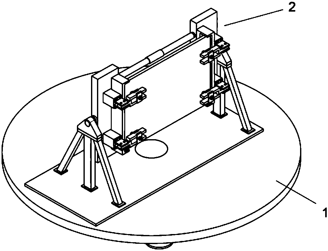
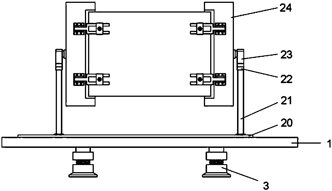
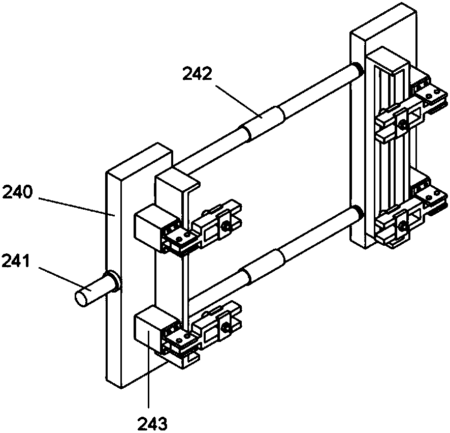
[0024] Such as Figure 1-8 As shown, a rotating support for a solar photovoltaic panel includes a base 1, a shock-absorbing component 3 is arranged on the lower part of the base 1, a connecting plate 20 is arranged on the upper part of the base 1, and a supporting mechanism 2 is arranged on the upper part of the connecting plate 20, and the supporting mechanism 2 includes two opposite The supporting leg 21 is set, the upper part of the supporting leg 21 is provided with a bearing mounting seat 22, and the bearing mounting seat 22 is provided with a bearing 23, and a rotating positioning member 24 is erected between the two supporting legs 21, and the rotating positioning member 24 includes two relative The positioning unit is provided ...


PUM


Abstract

The invention discloses a rotating bracket of a solar photovoltaic panel. The rotating bracket comprises a base, wherein the lower part of the base is provided with a shock absorbing part, the upper part of the base is provided with a connecting plate, the upper part of the connecting plate is provided with a bracket mechanism, the bracket mechanism comprises two supporting legs facing each other, the upper part of each supporting leg is provided with a bearing mounting base, a bearing is arranged in each bearing mounting base, a rotary positioning piece is arranged between the two supporting legs, the rotary positioning piece comprises two positioning units which face each other and are of the same structure, the two positioning units are connected by means of two telescopic connecting rods, each positioning unit comprises a positioning bracket and fixing blocks arranged at both ends of the positioning bracket, each positioning bracket comprises a supporting plate, the side surface of each supporting plate is provided with a rotating shaft, a positioning base is arranged on each supporting plate, each positioning base is in a long strip shape, the inner side of each positioning base is provided with an elastic strip, and insertion holes to be inserted by the telescopic connecting rods are formed in two end parts of the inner side of each supporting plate. The rotating bracket is simple in structure, realizes the rotation and fixation of the photovoltaic panel, and facilitates the maximum utilization of solar energy.

Description

Technical field: [0001] The invention relates to the technical field of photovoltaic panel supports, in particular to a rotating support for solar photovoltaic panels. Background technique: [0002] With the development and progress of society, the sustainable development of the environment and resources has attracted more and more attention, and the utilization of new energy has become more and more important. Among them, solar energy is a very clean and effective new energy source, and it is an inexhaustible clean energy source. Reasonable and effective use of solar energy plays a very important role in the protection of the social environment and the development of human society. The photovoltaic power generation device in the prior art is generally made of a photovoltaic panel as an integral board, which is fixed on a platform at a certain angle, such as the roof of a building or a base station, etc., and uses the energy of sunlight absorbed by the photovoltaic panel to ...

Claims


Application Information

Patent Timeline
Patent Type & Authority Patents(China)
IPC IPC(8): H02S20/30F24S30/425
CPCF24S30/425H02S20/30Y02E10/47Y02E10/50
Inventor 黄仕强田君福
Owner XIAMEN ANTAI NEW ENERGY TECH
Why Eureka
Eureka Blog
Learn More