A lane departure warning method and system

A technology of lane departure warning and lane line, which is applied in the field of automobile safety system, can solve the problems that the warning conditions are not set in detail, the alarm lacks a buffer stage, etc., and achieve the effect of reducing collision accidents and multi-response time

Active Publication Date: 2019-04-26
兴科迪科技(泰州)有限公司
View PDF10 Cites 1 Cited by
  • Summary
  • Abstract
  • Description
  • Claims
  • Application Information

AI Technical Summary

Problems solved by technology

However, the application did not involve the HUD head-up display, and the application for the invention did not make a detailed division of the setting of the warning conditions, so that the warning lacked a buffer stage

Method used


Image

  • A lane departure warning method and system
  • A lane departure warning method and system
  • A lane departure warning method and system

Examples


Embodiment 1

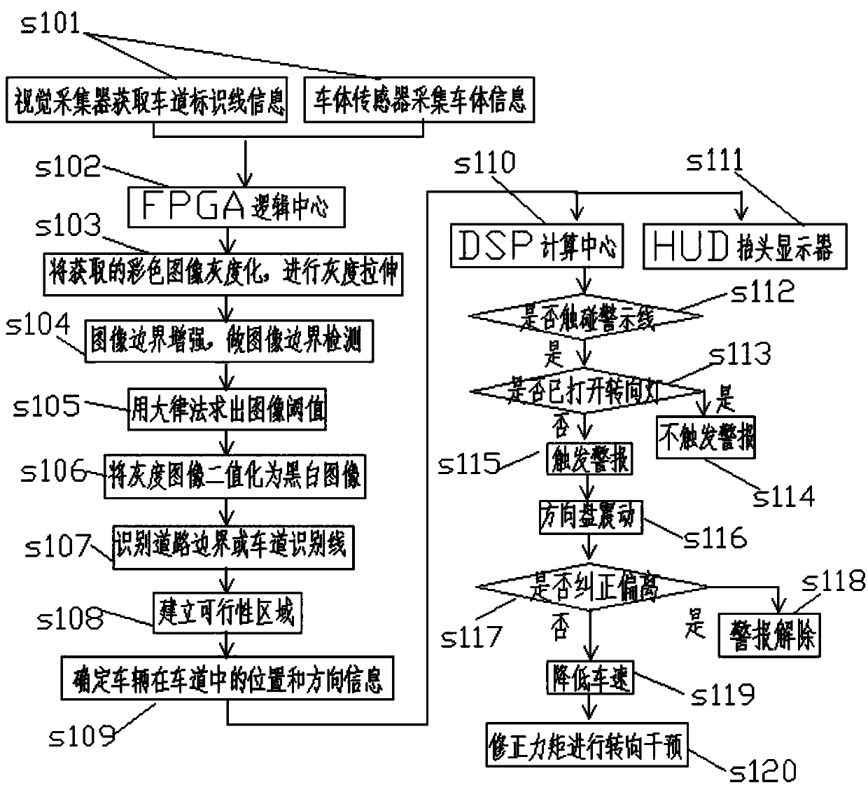
[0076] attached figure 1 It can be seen that a lane departure warning method comprises the following steps:

[0077] S101: The multifunctional camera installed behind the front windshield acquires lane marking line information in the road image, and the vehicle body information sensor collects vehicle body information; the vision collector includes a road condition information collector, and the road condition information collector includes at least The multi-function cameras on both sides of the windshield; the body information sensors include at least an infrared sensor installed at the bottom of the front end of the body;

[0078] S102: Provide the lane marking line information and vehicle body information to the FPGA logic center,

[0079] S103: the FPGA logic center grayscales the acquired color image, and performs grayscale stretching;

[0080] S104: Perform boundary enhancement processing on the image, and perform image boundary detection;

[0081] S105: Calculate th...

Embodiment 2

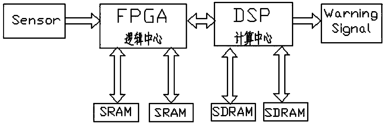
[0112] as attached figure 2 As shown, it is a lane departure warning system, including:

[0113] Vision collector: it is configured to obtain the lane marking information in the road image, and provide the information to the FPGA logic center; the vision collector includes a road condition information collector, and the road condition information collector includes at least two sensors installed on both sides of the front windshield. Multi-function camera; vehicle body information sensors include at least an infrared sensor installed at the bottom of the front end of the vehicle body;

[0114] Vehicle body information sensor: it is configured to be suitable for collecting vehicle body information and providing the vehicle body information to the FPGA logic center;

[0115] FPGA logic center: it is configured to convert the received information to determine the position and direction information of the own vehicle in the lane for image preprocessing, and transmit the preproce...


PUM


Abstract

Disclosed are a lane departure early warning method and system. The lane departure early warning method comprises the following steps: a vision collector obtaining lane mark line information of a road image, a vehicle body information sensor collecting vehicle body information, providing the lane mark line information and the vehicle body information to an FPGA logic center, and the FPGA logic center determining information of the location of a vehicle in the lane and the direction through conversions; the FPGA logic center providing the information of the location of the vehicle in the lane and the direction to a DSP computing center, and the DSP computing center determining whether an alarm is triggered or not under the current state according to set the early warning conditions; an alarm module receiving the warning information issued by the DSP computing center and performing vehicle body control according to the warning information; and arranging a head-up display HUD on glass in front of the head of a driver, wherein the display at least displays vehicle row parameters, as well as the information of the location of the vehicle in the lane and the direction. The lane departure early warning method and system can assist in the conditions of inattention and the like due to over-fatigue or long-term monotonous driving.

Description

technical field [0001] The invention relates to the field of automobile safety systems, in particular to a lane departure warning method and system. Background technique [0002] The U.S. Federal Highway Administration estimates that 44% of all fatal traffic accidents in the United States in 2002 were related to lane departure, and lane departure is also regarded as the main cause of vehicle rollover accidents. Analysis results of the AssitWare website: 23% of car drivers fall asleep on the steering wheel at least once a month; 66% of truck drivers themselves doze off during driving; The experience of falling asleep at the wheel. That is to say: one in four drivers has experienced a fatal accident caused by lane departure. [0003] The invention patent application with the application number of 201210442546.3 discloses a lane departure warning system, which includes a plurality of sensing units, at least one communication channel, a computing module and a warning signal ge...

Claims


Application Information

Patent Timeline
Patent Type & Authority Patents(China)
IPC IPC(8): B60W50/16B60W50/14
CPCB60W50/14B60W50/16B60W2552/00B60W2552/20
Inventor 白云飞李全睿
Owner 兴科迪科技(泰州)有限公司
Why Eureka
Try Eureka