
An angular vibrating table
A technology of angular vibration table and stage, which is applied in vibration testing, testing of machine/structural components, measuring devices, etc. It can solve the problems of large voice coil motor load, limited size of the tested part, and low displacement execution accuracy. , to achieve the effect of accurate rotation, no need for assembly, and not easy to fatigue and fracture
- Summary
- Abstract
- Description
- Claims
- Application Information
AI Technical Summary
Problems solved by technology
Method used
Image

Examples
Embodiment Construction
[0027] The present invention will be further described below in conjunction with accompanying drawing.
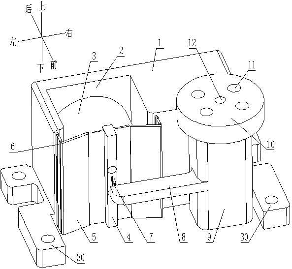
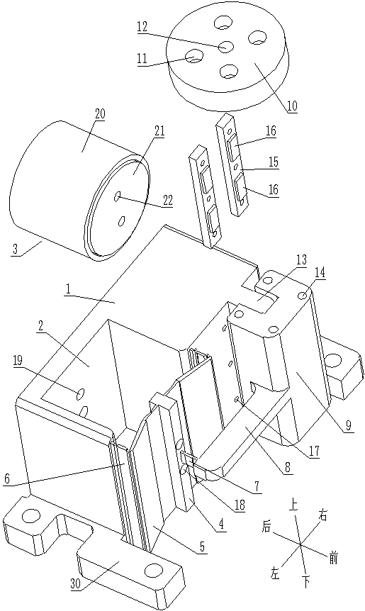
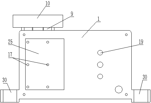
[0028] like Figure 1-Figure 4 An angular vibrating table shown includes a base 1, a rotating support located on the front side of the base 1, and a stage 10 fixedly connected to the rotating support; between the right part of the rotating support and the base 1 Connected by a first flexible hinge 23, the rotation axis of the first flexible hinge 23 is set along the up and down direction; a connecting block 4 is arranged between the left part of the rotating support and the seat 1, and the left part of the connecting block 4 and the rotating supporting They are connected by a flexible transmission structure, and the connection block 4 and the base body 1 are connected by a guide mechanism; the voice coil actuator 3 is fixedly installed on the base body 1, and the output end of the voice coil actuator 3 is fixed to the connection block 4 connected, the voice coil actuator 3...
PUM
 Abstract
Description
Claims
Application Information