
A special liquid injector for municipal landscaping and its use method
A landscaping and liquid injector technology, which is applied in the field of municipal landscaping, can solve problems such as inability to deliver liquid medicine normally, tree blockage, etc., so as to avoid needle blockage and improve work efficiency.
- Summary
- Abstract
- Description
- Claims
- Application Information
AI Technical Summary
Problems solved by technology
Method used
Image

Examples
Embodiment 1
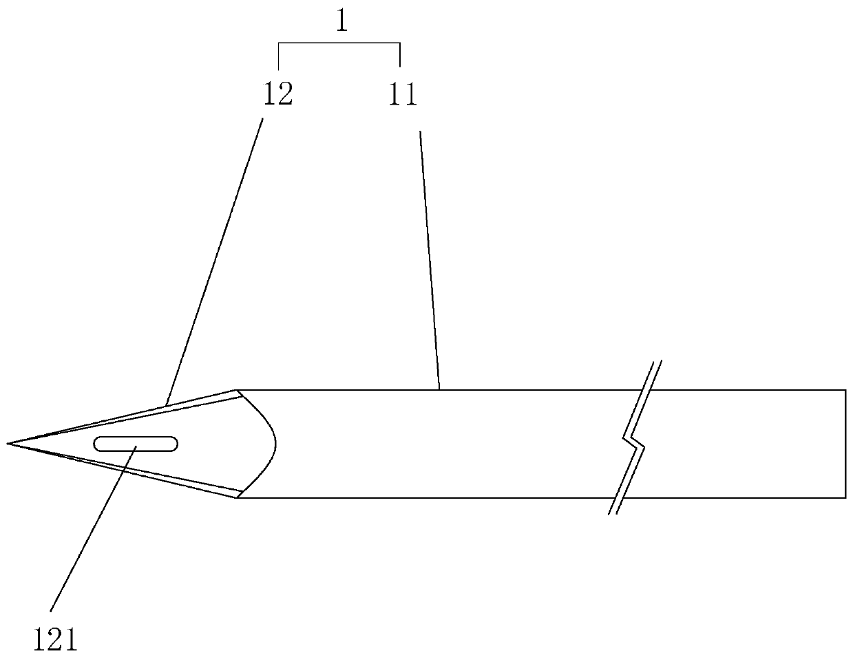
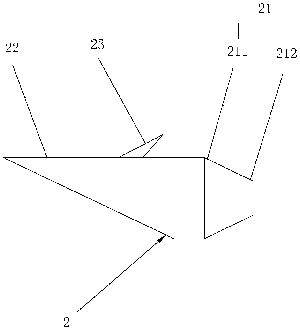
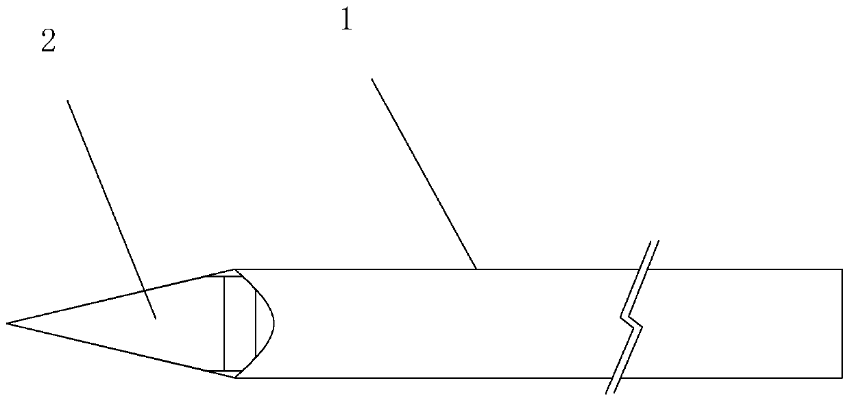
[0031] Embodiment 1: as Figure 1 to Figure 3 As shown, a special injector for municipal landscaping includes a needle head 1, the needle head 1 is divided into a needle tube 11 and a needle point 12, a plug 2 is provided at the needle point 12, and one end of the plug 2 is a plug that can be inserted into the needle tube 11 The connecting end 21 and the other end are sharp needles 22 , and the plug 2 is also provided with barbs 23 opposite to the needles 22 . The side wall of the needle point 12 is provided with a waist groove 121, the length direction of the waist groove 121 is consistent with the axial direction of the needle tube 11, the barb 23 is inserted into the waist groove 121 to form a sliding connection with the waist groove 121, and the barb 23 penetrates Pass through the waist groove 121 and protrude from the outer wall of the needle point 12, and set the barb 23 on the plug 2 in the waist groove 121 of the needle point 12, so that after the injection is complete...
Embodiment 2
[0034] Embodiment 2: The difference between Embodiment 2 and Embodiment 1 lies in the waist groove 121, such as Figure 6 shown, combined with figure 2 In Embodiment 2, the width of the waist groove 121 near the needle tip 12 is smaller than the width at the other end, and the barb 23 forms a transition fit or an interference fit with the minimum width of the waist groove 121 . When the needle 1 moves back slightly, the barb 23 is clamped with the narrower end of the waist groove 121, and the plug 2 is more firmly connected to the needle 1 when it is pulled out. In addition, it also provides a supporting force for the needle 1 to prevent The needle is pressed against the plug 2 once and combined with it.
PUM
 Abstract
Description
Claims
Application Information