Micro-structured mixer

A micro-structure mixer and fluid mixing technology, which is applied in the direction of fluid mixers, mixers, chemical instruments and methods, etc., can solve problems such as blockage, limited popularization and use, and high requirements for cleanliness, and achieve easy processing and amplification , broad prospects for promotion and application, and low requirements for material cleanliness

Active Publication Date: 2013-01-02
TSINGHUA UNIV
View PDF1 Cites 7 Cited by
  • Summary
  • Abstract
  • Description
  • Claims
  • Application Information

AI Technical Summary

Problems solved by technology

Once this happens, the velocity of fluid through that pore is drastically reduced, making further clogging more likely
Therefore, the microporous structure mixer often has high requirements on the cleanliness of the material, which limits its promotion and use

Method used


Image

  • Micro-structured mixer
  • Micro-structured mixer
  • Micro-structured mixer

Examples


Embodiment 1

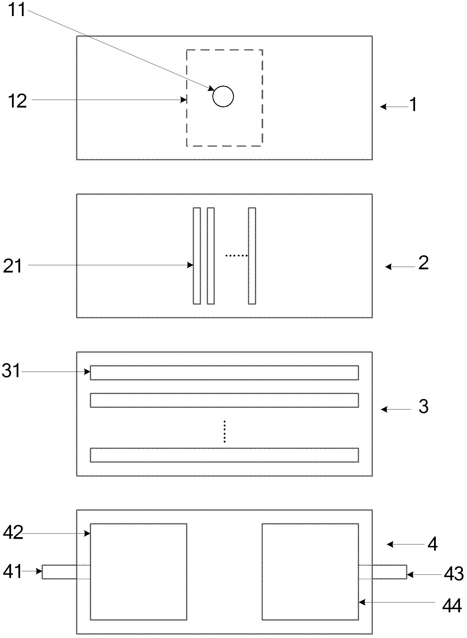
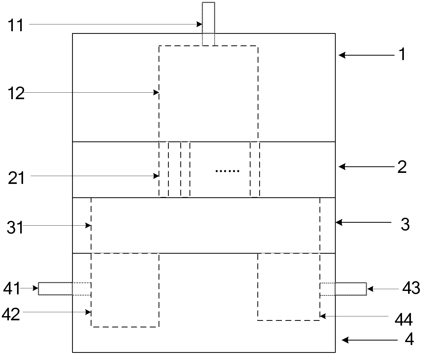
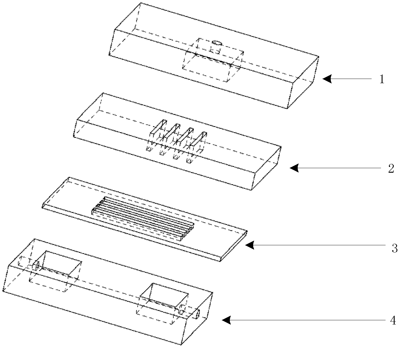
[0040] A microstructure mixer, the microstructure mixer is formed by sequentially stacking a first interface plate 1, a first fluid distribution plate 2, a fluid mixing plate 3 and a second interface plate 4; wherein,

[0041] The first interface plate 1 is provided with a first fluid inlet pipe 11 and a first fluid buffer chamber 12;

[0042] The first fluid distribution plate 2 is provided with at least one through groove 21;

[0043] The fluid mixing plate 3 is provided with at least one through groove 31;

[0044] The second interface plate 4 is provided with a second fluid inlet pipe 41, a second fluid buffer chamber 42, a mixed fluid buffer chamber 44 and a mixed fluid outlet pipe 43;

[0045] The channel 21 provided on the first fluid distribution plate 2 communicates with the first fluid buffer chamber 12 .

[0046] The through-groove 31 provided on the fluid mixing plate 3 and the through-groove 21 provided on the first fluid distribution plate 2 have micro-groove c...

Embodiment 2

[0052] A microstructure mixer, the number of through grooves on the first fluid distribution plate is 20, the width of each through groove is 0.4mm, and the aspect ratio is 1000. The number of through grooves on the fluid mixing plate is 20, the width of each through groove is 10mm, and the depth is 3mm.

[0053] The channel 21 provided on the first fluid distribution plate 2 is a parallel channel, and the channel 31 provided on the fluid mixing plate 3 is a parallel channel. All the other are identical with embodiment 1.

[0054] A solution flow rate is 20m 3 / h, the flow rate of solution B is 4m 3 / h, Xs was measured to be 0.003.

Embodiment 3

[0056] A microstructure mixer, the number of through grooves on the first fluid distribution plate is 5, the width of each through groove is 1 mm, and the aspect ratio is 100. The number of through grooves on the fluid mixing plate is 10, the width of each through groove is 5mm, and the depth is 2mm. All the other are identical with embodiment 2.

[0057] A solution flow rate is 2m 3 / h, the flow rate of solution B is 0.5m 3 / h, Xs was measured to be 0.002.


PUM


Abstract

The invention discloses a micro-structured mixer, which belongs to the technical field of chemical and chemical engineering. The micro-structured mixer is formed by stacking a first interface board, a first fluid distributing plate, a fluid mixing plate and a second interface board in sequence, wherein the first interface board is provided thereon with a first fluid inlet pipe and a first fluid buffer chamber, the first fluid distributing plate is provided thereon with at least one through slot, the fluid mixing plate is provided thereon with at least one through slot, the second interface board is provided thereon with a second fluid inlet pipe, a second fluid buffer chamber, a mixed fluid buffer chamber and a mixed fluid outlet pipe, when the number of the through slots arranged on the first fluid distributing plate is larger than one, the arranged through slots are parallel through slots, when the number of the through slots arranged on the fluid mixing plate is larger than one, the arranged through slots are parallel through slots. The treatment capacity of unit volume of the micro-structured mixer is larger, the micro-structured mixer is easy to store and enlarge, has low requirement for material cleanliness, and can be used in chemical, chemical engineering, petrochemical, medicine and food industries.

Description

technical field [0001] The invention belongs to the technical field of chemistry and chemical engineering, and in particular relates to fluid micro-mixing technology and equipment, which can be used in the mixing or reaction process between different fluids. In particular, it relates to a microstructure mixer. Background technique [0002] Traditional chemical reactors or mixers mainly use stirring to mix. Although the principle of this mixing method is simple, because the mixing scale in the equipment is at the millimeter level or even larger, the mixing efficiency is low and the energy consumption of the mixing process is low. Big question. Although tower-type, tubular-type reactors or mixers in the traditional sense have their own characteristics relative to full-mixing tanks, they also have low mixing efficiency because they are also in the range of millimeter-scale mixing with stirring equipment. The problem. At the same time, because these devices adopt the method o...

Claims


Application Information

Patent Timeline
Patent Type & Authority Applications(China)
IPC IPC(8): B01F5/00
Inventor 吕阳成骆广生刘振东
Owner TSINGHUA UNIV
Why Eureka
Try Eureka