Combined pile casing for power transmission tower foundation

A shielding and foundation technology, which is applied in the field of combined shielding, can solve the problems that large-scale equipment is difficult to complete the lifting work, the construction conditions of special engineering pile foundations are poor, and the risk of surface subsidence increases, so as to avoid unstable installation and improve lifting efficiency. , the effect of reducing the difficulty of promotion

Inactive Publication Date: 2017-05-24
CHINA ELECTRIC POWER RES INST +1
View PDF5 Cites 1 Cited by
  • Summary
  • Abstract
  • Description
  • Claims
  • Application Information

AI Technical Summary

Problems solved by technology

like figure 1 The direct lifting method shown is to use the lifting mechanical equipment to pull the casing out of the borehole along the axis of the drilling hole. Obviously, the lifting force must be greater than the outer frictional resistance of the casing. The problems of this method include: 1) The lifting force is large, Therefore, large-scale hoisting and lifting machinery or special special equipment are required; 2) The lifting machinery or equipment has a large downward pressure on the ground surface, so the risk of surface subsidence increases and even affects the stability of the borehole wall; 3) Pile foundation construction for special projects such as power transmission lines The conditions are harsh, large-scale equipment is limited and cannot enter the site, and it is difficult to complete the promotion work
The problems of this method are: 1) it has good applicability to non-cohesive soil with high water content, but it has poor effect on soil layers with other conditions; 2) it will cause noise pollution to the surrounding environment; 3) the drag reduction and lifting effect of vibratory hammer is not good. Ideally, there will be various problems encountered in direct promotion as listed above

Method used


Image

  • Combined pile casing for power transmission tower foundation
  • Combined pile casing for power transmission tower foundation
  • Combined pile casing for power transmission tower foundation

Examples


Embodiment 1

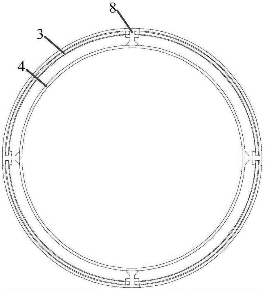
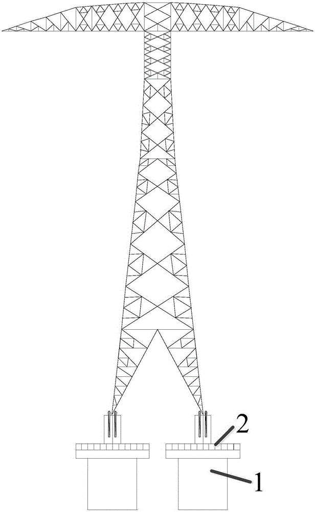
[0042] Such as figure 1 and figure 2 As shown, a combined casing for foundation construction of a transmission tower, the foundation of the transmission tower includes a concrete foundation 1 and a cap 2 arranged on the upper end of the concrete foundation 1, and the composite casing includes an outer steel casing 3 and the inner steel casing 4 socketed in the inner cavity of the outer steel casing 3,

[0043] The upper end of the platform 2 is provided with a fixing assembly 5 for fixing the transmission tower,

[0044] Between the outer steel casing 3 and the inner steel casing 4 , an I-shaped casing connector 8 connecting the casings is arranged in a direction perpendicular to the axis of the composite casing.

[0045] The cap 2 includes a bottom plate 6 and a fixed beam 7 arranged sequentially on the upper end of the concrete foundation 1;

[0046] The bottom plate 6 is a reinforced concrete slab,

[0047] The fixed beam 7 is a reinforced concrete slat arranged transv...


PUM


Abstract

The invention relates to a combined pile casing for a power transmission tower foundation. The power transmission tower foundation comprises concrete foundation bodies and bearing platforms, wherein each bearing platform is arranged at the upper end of the corresponding concrete foundation body. The combined pile casing comprises an outer steel pile casing body and an inner steel combined pile casing body which is arranged in an inner chamber of the outer steel pile casing body in a sleeved manner. The upper end of each bearing platform is provided with a fixing assembly for fixing a power transmission tower. H-shaped pile casing connecting pieces for connecting the pile casing bodies are arranged between the outer steel pile casing body and the inner steel combined pile casing body in the direction perpendicular to the axis of the combined pile casing. The combined pile casing for constructing the power transmission tower foundation has the beneficial effects that the power transmission tower fixing requirement in a mollisol area can be met; and the combined pile casing is low in production cost, convenient to mount and firm.

Description

technical field [0001] The invention relates to a construction equipment, in particular to a combined casing used for the foundation of an electric tower. Background technique [0002] During the construction of the foundation of the transmission tower, when the drilled hole passes through the soft flow-plastic soil layer, the collapse hole, the infiltration of surface water into the foundation and the instability of the foundation pile often occur. Therefore, it is necessary to provide a combined casing for the foundation construction of the transmission tower to ensure The normal construction of the tower foundation is not affected by collapsed holes and unstable pile positions. [0003] The existing composite casing adopts direct lifting or vibrating hammer lifting. Such as figure 1 The direct lifting method shown is to use the lifting mechanical equipment to pull the casing out of the borehole along the axis of the drilling hole. Obviously, the lifting force must be gr...

Claims


Application Information

Patent Timeline
Patent Type & Authority Applications(China)
IPC IPC(8): E02D5/66E02D5/38E02D27/42
Inventor 贺雷刘华清赵斌滨王建勋
Owner CHINA ELECTRIC POWER RES INST
Why Eureka
Try Eureka