Relative radiometric calibration method for tdi scanning imaging system adapting to multi-channel bidirectional output

A technology of relative radiation calibration and two-way output, applied in radiation pyrometry, optical radiation measurement, instruments, etc., can solve the problems of image strong pattern noise, affecting imaging quality, high data transfer rate of TDI devices, etc., to achieve the correction of relative radiation Effect of Calibration Accuracy

Active Publication Date: 2019-04-19
TIANJIN JINHANG INST OF TECH PHYSICS
View PDF5 Cites 0 Cited by
  • Summary
  • Abstract
  • Description
  • Claims
  • Application Information

AI Technical Summary

Problems solved by technology

The TDI scanning imaging system mainly includes an optical system and a photodetector device. On the one hand, there is vignetting in the optical system, that is, the uniform target is transformed by the optical system to redistribute the energy, resulting in the concentration of energy at the center of the focal plane and gradually decreasing to the edge, resulting in The energy distribution on the focal plane is uneven; on the other hand, due to the intrinsic characteristics of the material, the response characteristics of each detection pixel to the same energy input are different, resulting in uneven response; secondly, the data transfer rate of the TDI device is high, and the device often uses The multi-channel output structure meets the high-frequency data transfer, and the image produces channel block effect due to different channel signals passing through different paths and different operational amplifiers.
The inconsistency caused by the combined effects of these three factors will cause strong pattern noise in the acquired image, seriously affecting the imaging quality, and is an important and key factor restricting the multi-channel TDI scanning imaging system.

Method used


Image

  • Relative radiometric calibration method for tdi scanning imaging system adapting to multi-channel bidirectional output
  • Relative radiometric calibration method for tdi scanning imaging system adapting to multi-channel bidirectional output
  • Relative radiometric calibration method for tdi scanning imaging system adapting to multi-channel bidirectional output

Examples


Embodiment

[0046] In this example:

[0047] (1) Detailed operation method of step 4

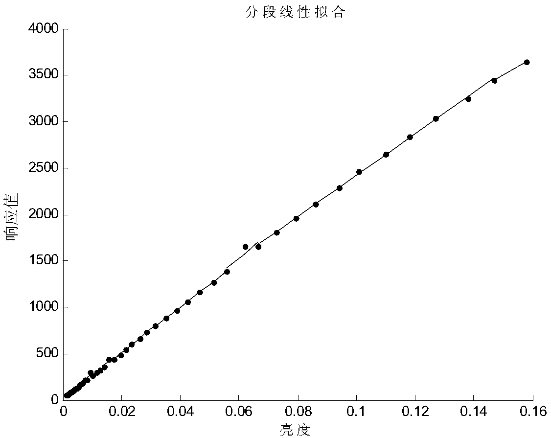
[0048] There are a finite number of data radiation linear functions, which meet

[0049] f(L i ) m =a m ·L mi +b m (1)

[0050] In the formula:

[0051] m—divided segment;

[0052] L mi — the i-th radiance in the m segment;

[0053] f(L i ) m —Any input luminance L in this segment i , according to the average gray level of the image solved by formula (1);

[0054] a m — the slope of the segment conforming to a linear response;

[0055] b m — the intercept of the radiation linear response in this segment;

[0056] —Input radiance L in segment m i When , the average gray level of the image is collected.

[0057] a m , b m The solution is as follows:

[0058] Let the deviation between the data of each sampling point and the fitting data be The sum of squared deviations is Calculate the partial derivative of the sum of squared deviations and sort it out:

[0059]

[0060] The ...


PUM


Abstract

The invention belongs to the technical field of relative radiation calibration, and in particular relates to a relative radiation calibration method for a TDI scanning imaging system adapting to multi-channel bidirectional output. The method includes recording the maximum radiance, recording luminance data at intervals, calculating multi-channel average radiation response data, linearly segmenting the collection points, performing two-point relative radiation calibration correction for each segment, and recording the average gray value of the first and last images of each segment. Steps such as typical values ​​of radiance, selection of corresponding relative radiation calibration coefficients, etc. Compared with the prior art, the present invention solves the problem of relative radiation calibration of a multi-channel TDI scanning imaging system, not only can control the relative radiation calibration accuracy in a single channel, but also can correct the relative radiation calibration accuracy between channels.

Description

technical field [0001] The invention belongs to the technical field of relative radiation calibration, and in particular relates to a relative radiation calibration method for a TDI scanning imaging system adapting to multi-channel bidirectional output. Background technique [0002] At present, the military and civilian aspects of optical remote sensing imaging systems are increasingly required to have the ability to acquire large-scale wide, high signal-to-noise ratio target images. In order to obtain large wide, high signal-to-noise ratio target images, TDI scanning imaging is usually used. The TDI scanning imaging system mainly includes an optical system and a photodetector device. On the one hand, there is vignetting in the optical system, that is, the uniform target is transformed by the optical system to redistribute the energy, resulting in the concentration of energy at the center of the focal plane and gradually decreasing to the edge, resulting in The energy distri...

Claims


Application Information

Patent Timeline
Patent Type & Authority Patents(China)
IPC IPC(8): G01J5/00
CPCG01J5/00G01J5/80
Inventor 霍家全王珊珊付海涛
Owner TIANJIN JINHANG INST OF TECH PHYSICS
Why Eureka
Try Eureka