LED box

A technology of LED box and LED light board, applied in the direction of instruments, static indicators, etc., can solve the problems of driving ability interference, unable to support loading, abnormal display, etc., to improve stability and reliability, and avoid multi-level driving and wiring, reducing the effect of the problem

Active Publication Date: 2017-05-31
XIAN NOVASTAR TECH
View PDF5 Cites 2 Cited by
  • Summary
  • Abstract
  • Description
  • Claims
  • Application Information

AI Technical Summary

Problems solved by technology

[0005] However, in the existing scanning card, due to the need to have relatively complete functionality, the scanning card needs to receive data from the front-end sending card through the network, and at the same time output the image display driving signal through the standard HUB interface. In this way, FPGA and its supporting Related devices, driver chips for output signal enhancement, etc., lead to a relatively large volume of the scanning card, which makes it unsuitable for the application of small-pitch LED displays; at the same time, the bandwidth of the scanning card is limited and it is difficult to support a large bandwidth. In addition, in the existing LED display control system, the HUB board design and the failure problems in the LED light board module connection accounted for a considerable proportion, mainly reflected in the complicated signal distribution and The interference problem caused by insufficient drive capability due to different cable lengths is more serious; moreover, because each LED light board module needs multiple sets of display data (R, G, B data) and a set of control signals (clock signal CLK, lock storage signal LAT, enable signal OE, and row selection signals A, B, C, etc.), and there may be a set of monitoring module communication interfaces, so that when loading more data groups, there will be many signals that need to be rearranged In this process, interface errors or unreasonable signal wiring often occur, resulting in abnormal display or affected display effects; in addition, the general HUB board will be connected to the LED light board module through the cable, while the LED The image display driving signal (display data signal and control signal) required by the light board module needs to go through the multi-level drive on the scanning card and the HUB board to ensure the normal transmission of the signal, and the multi-level drive often introduces signal distortion and delay, etc. Uncontrollable problems, which will greatly affect the normal display effect of the LED display, and the enhanced drive will increase the signal radiation, making it difficult for the product to pass the EMC certification

Method used


Image

  • LED box
  • LED box
  • LED box

Examples


Embodiment Construction

[0026] In order to make the above objects, features and advantages of the present invention more comprehensible, specific implementations of the present invention will be described in detail below in conjunction with the accompanying drawings.

[0027]Specifically, the following embodiments of the present invention propose that the functions of the scanning card be chip-based as much as possible to solve the problems of signal transmission and HUB wiring in the existing LED display control system, and at the same time reduce the volume of the scanning card and support a larger load. , supports small-pitch screens, and even solves the signal stability and reliability problems in cascading and multi-stage transmission of existing scanning cards in signal processing, reduces EMI, and more efficiently meets customer EMC requirements.

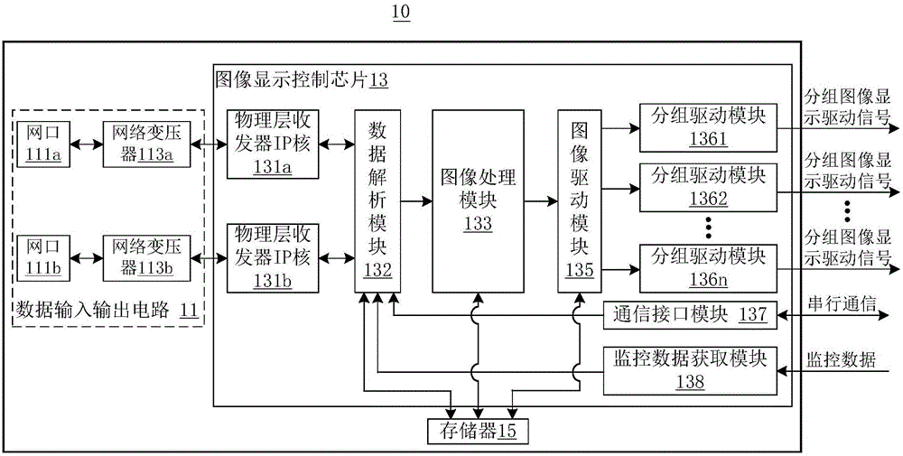
[0028] see figure 1 , which is a schematic structural diagram of a scanning card according to an embodiment of the present invention. Such as fig...


PUM


Abstract

The invention provides an LED box. The LED box comprises a scanning card and a plurality of LED lamp panel modules connected to the scanning card, wherein the scanning card comprises an image display control chip; the image display control chip is used for receiving a data packet input from the outside and unpacking the data packet, carrying out classifying treatment on the data obtained after unpacking, carrying out image capturing (in a manner of corresponding to the size of a loading area of the scanning card), correcting treatment, gray level separation and data rearrangement on the image data obtained after classifying treatment, so that image display drive signals are generated, and carrying out grouping treatment on the image display drive signals so that at least one path (such as a plurality of paths) of grouped image display drive signals is output to the plurality of LED lamp panel modules. According to the LED box, the function of the scanning card is made chip-based to the greatest extent, and thus the purposes of reducing the size of the scanning card and improving the display effect of an LED display screen body are achieved.

Description

technical field [0001] The invention relates to the field of display technology, in particular to an LED display screen control system. Background technique [0002] With the development of technology and the progress of society, LED display screens are more and more widely used in daily life. The commonly used LED display screen control system mainly includes sequentially connected video sources, video processors, sending cards, scanning cards and LED display screens. The display screen, and the scanning card is generally installed in the LED box with the HUB board (also called the adapter board). At the same time, the HUB port on the HUB board will be connected to multiple LED light board modules for cascade display through cables or pins. In this way, an LED box is formed, and multiple LED boxes are spliced ​​into an LED display. [0003] With the development of indoor small-pitch LED displays, more and more pixels need to be loaded by the scanning card. However, due to ...

Claims


Application Information

Patent Timeline
Patent Type & Authority Applications(China)
IPC IPC(8): G09G3/32
CPCG09G3/32
Inventor 刘德福王伙荣
Owner XIAN NOVASTAR TECH
Why Eureka
Try Eureka