Inverse time lag current protection method

A technology of inverse time protection and current protection, which is applied in the direction of protection that reacts to overcurrent, and can solve the problems of long action time of inverse time protection and limited application range.

Active Publication Date: 2017-06-09
CHINA ELECTRIC POWER RES INST +2
View PDF2 Cites 10 Cited by
  • Summary
  • Abstract
  • Description
  • Claims
  • Application Information

AI Technical Summary

Problems solved by technology

[0005] The action performance of the traditional zero-sequence current inverse time protection is limited by the wiring mode of the line. In the case of boosting current in the lower line, the boosting current will cause the inverse time limit leapfrog action; at the same time, when the fault current is small, The action time of inverse time limit protection is longer
Therefore, the scope of application of inverse time protection is easily limited

Method used


Image

  • Inverse time lag current protection method
  • Inverse time lag current protection method
  • Inverse time lag current protection method

Examples


Embodiment Construction

[0083] The specific implementation manners of the present invention will be further described in detail below in conjunction with the accompanying drawings.

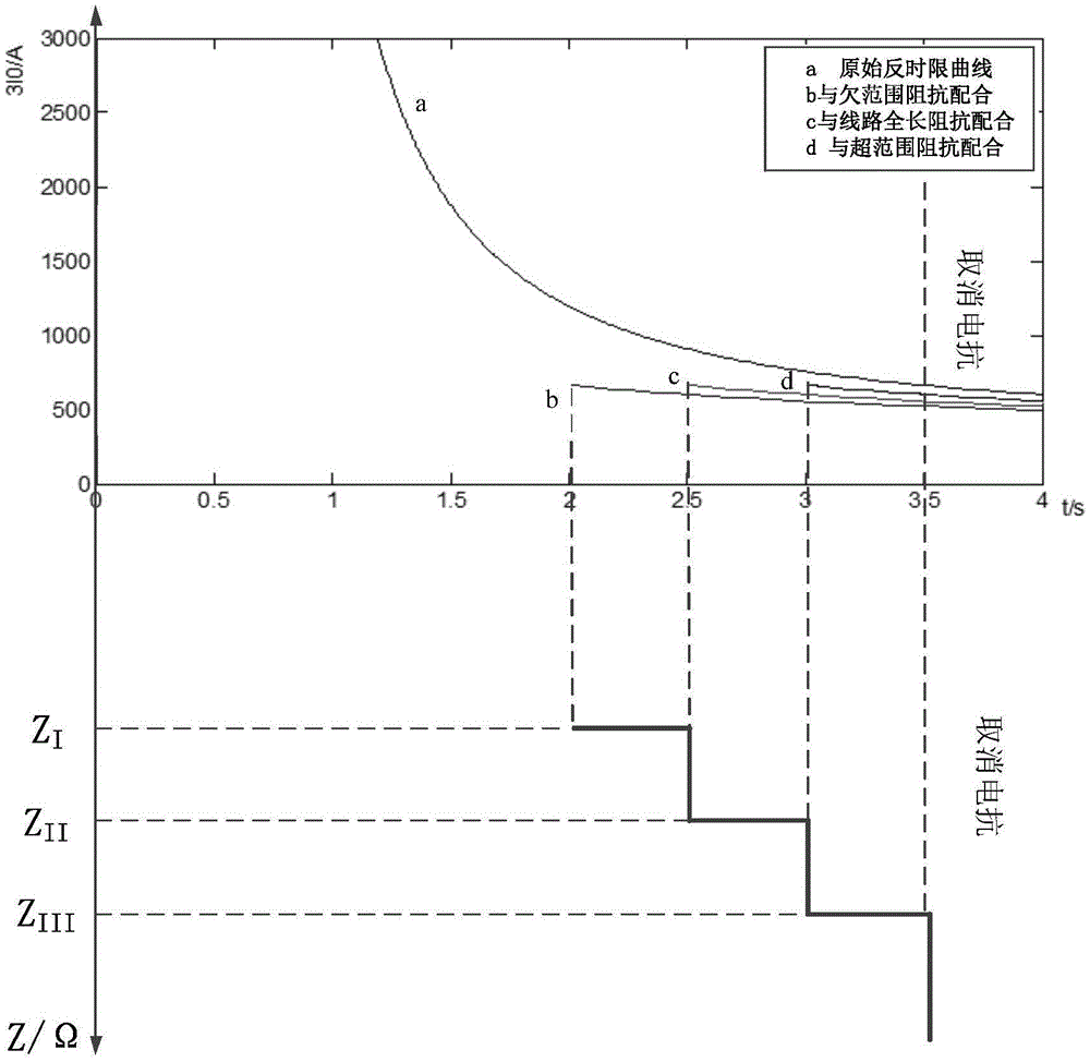
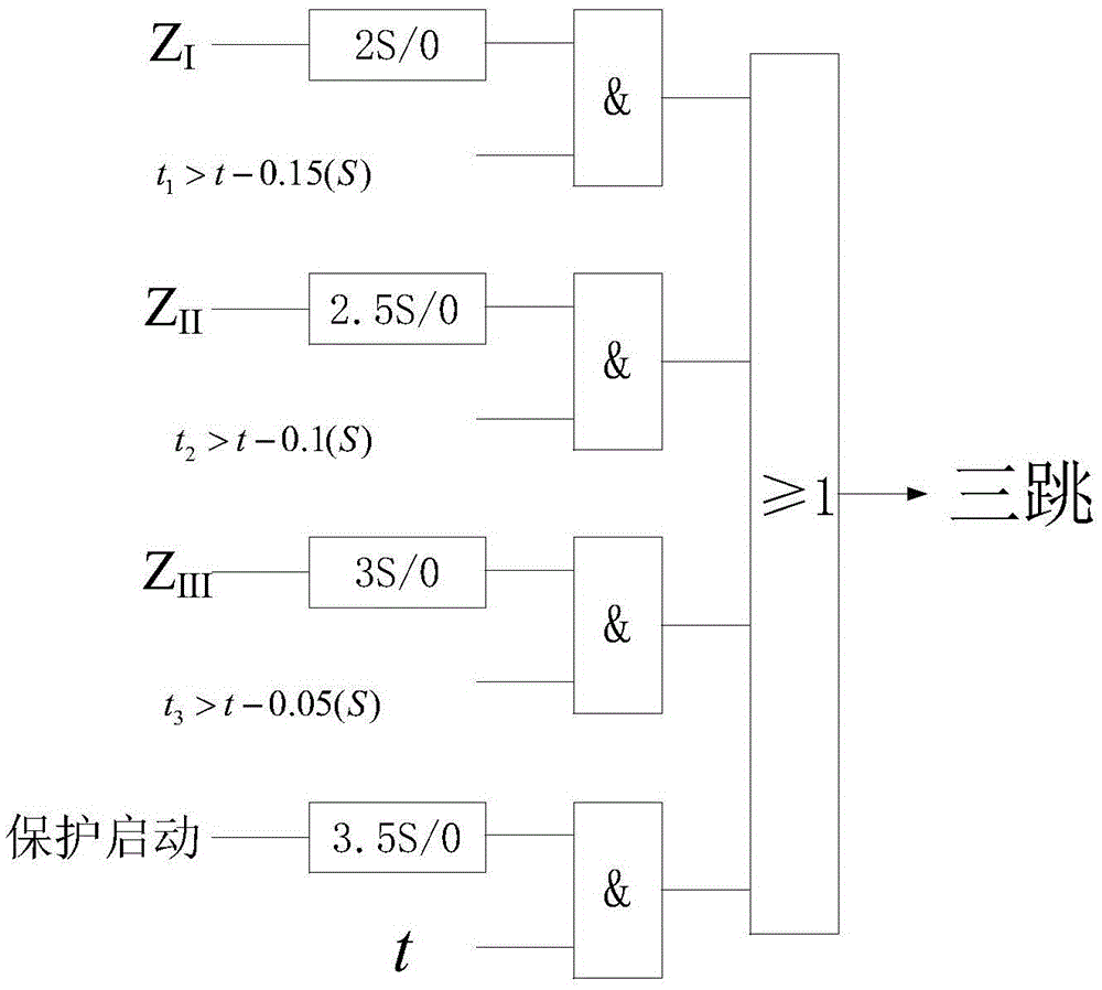
[0084] 1. The action equations of the high-resistance distance relays at the three-phase A, B and C of the acquisition protection installation are different for the transmission line, and the high-resistance distance relays at both ends of the transmission line are different. Take the A-phase high-resistance grounding fault as an example:

[0085] 1) sending end

[0086] ① High-resistance distance relay under-range section Z I Action equation:

[0087]

[0088] In the formula: I n is the secondary rated current of the current transformer, I BC is the BC phase-to-phase current, φ Z1 is the line positive sequence impedance angle, is the phase A compensation voltage, is the A-phase compensation voltage before the fault, Compensate the voltage variation for phase A.

[0089] Z I Action after 2 second...


PUM


Abstract

The invention relates to an inverse time lag current protection method. The method comprises steps that (1), the motion delay time of a sending and a receiving end of a high resistance distance relay is respectively calculated when protection mounting portions A, B and C are in three-phase faults; (2), the zero sequence current inverse time lag protection motion time of the sending end and the receiving end of the three-phase high resistance distance relay is respectively calculated; and (3), time relationships between high resistance distance protection and zero sequence current inverse time lag motion protection of the sending end and the receiving end of the three-phase high resistance distance relay are determined. The method is for zero sequence current inverse time lag protection and distance protection matching, a general fault scope can be determined through distance protection, a zero sequence current inverse time lag protection motion speed is accelerated, the inverse time lag protection motion time can be effectively shortened, skip-level motion can be prevented, and motion performance of zero sequence current inverse time lag protection under high resistance fault conditions is improved.

Description

technical field [0001] The invention relates to an inverse-time-limit current protection method, in particular to a method for coordinating inverse-time-limit current protection and distance protection. Background technique [0002] The action time of the inverse time overcurrent protection is related to the fault current and changes with the magnitude of the short-circuit current. The short-circuit current is large, the action time is fast, and the short-circuit current is small, the action time is slow, showing an inverse time-limit characteristic. The action time of relay protection is related to the magnitude of the short-circuit current, which is inversely proportional. [0003] Inverse time overcurrent protection is widely used in the protection of generators, transformers, motors and distribution networks. In order to meet the requirements of different equipment for inverse time-lag characteristic curves, the microcomputer protection device needs to provide a variety...

Claims


Application Information

Patent Timeline
Patent Type & Authority Applications(China)
IPC IPC(8): H02H3/08
Inventor 王兴国柳焕章周泽昕郭雅蓉杜丁香
Owner CHINA ELECTRIC POWER RES INST
Why Eureka
Try Eureka