
Split-type steel top steel skirt piston

A split-type, piston technology, used in pistons, engine components, machines/engines, etc., can solve the problems of excessively heavy oil cavity wall, piston ring seal failure, poor heat dissipation effect of steel pistons, etc., to achieve good hardness and strength, improve The effect of heat dissipation and stable operation

Pending Publication Date: 2019-07-09
象山浦动机械科技有限公司
View PDF0 Cites 1 Cited by
  • Summary
  • Abstract
  • Description
  • Claims
  • Application Information

AI Technical Summary

Problems solved by technology

[0004] In view of the above-mentioned deficiencies, the object of the present invention is to provide a split steel top and steel skirt piston to solve the problems of the steel piston in the prior art due to the heavy weight and the thick wall surface of the oil chamber of the integral middle grooved steel piston. Poor heat dissipation and the failure of the piston ring seal when the steel piston is running

Method used


Image

  • Split-type steel top steel skirt piston
  • Split-type steel top steel skirt piston
  • Split-type steel top steel skirt piston

Examples


Embodiment 1

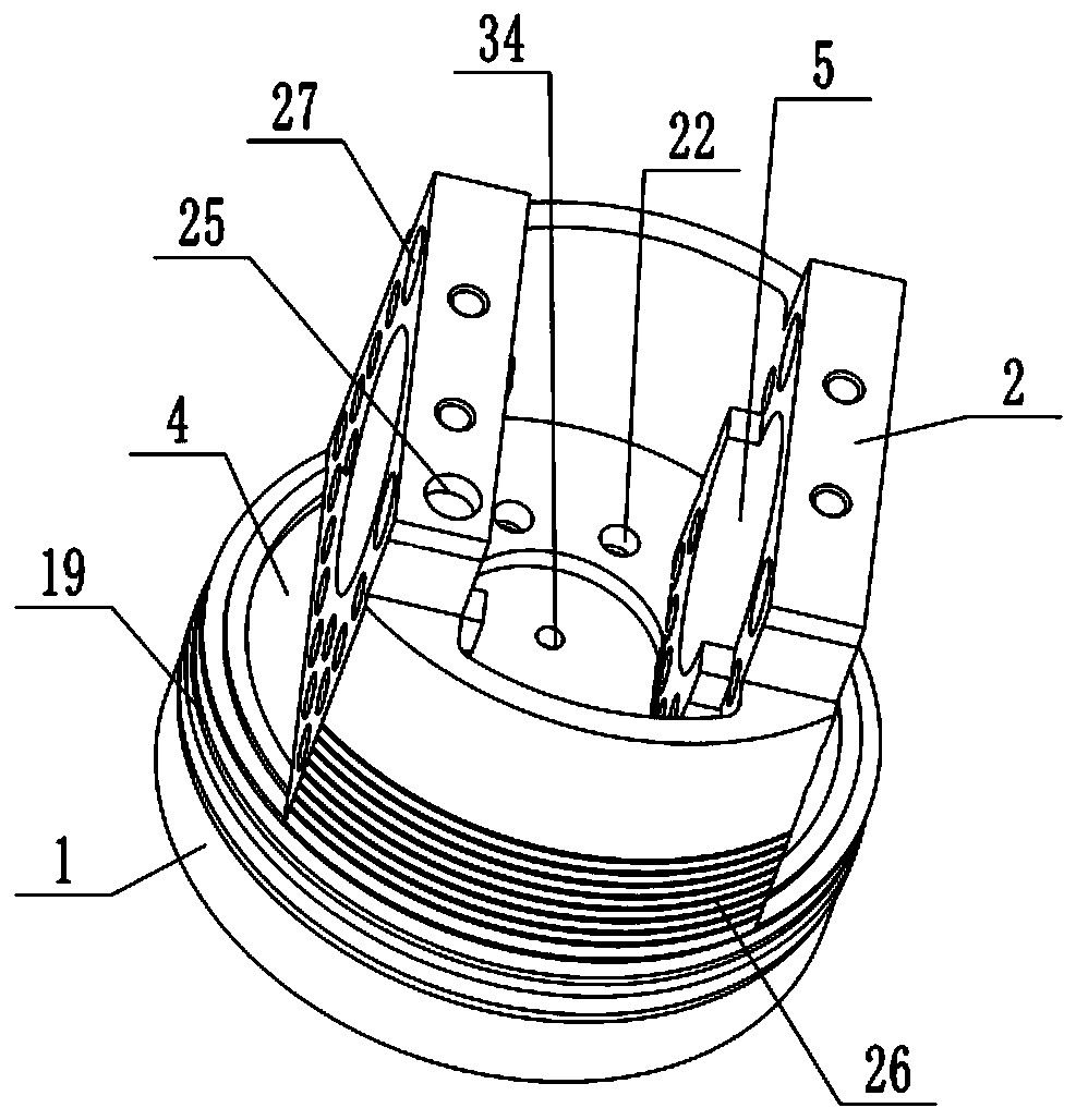
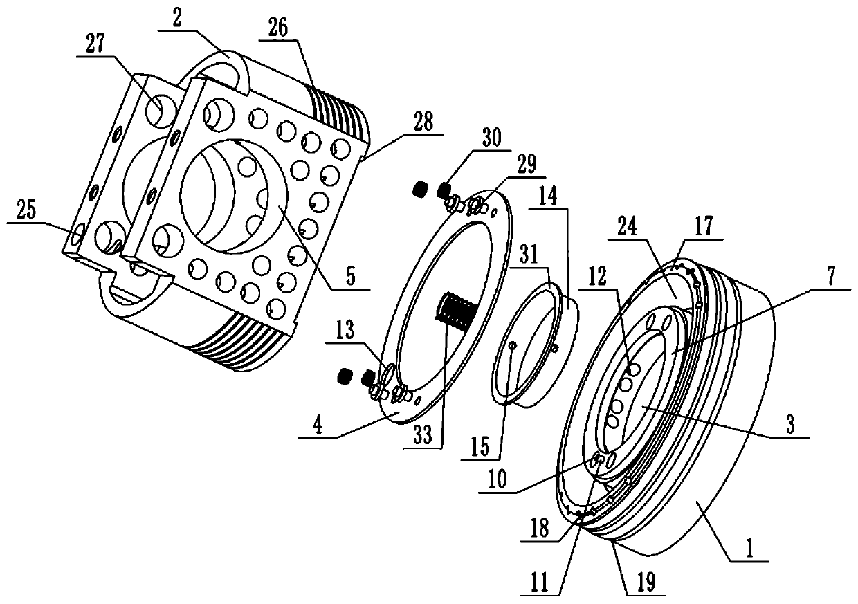
[0034] Embodiment one is basically as attached Figure 1 to Figure 5 Shown:

[0035] The split type steel top and steel skirt piston includes the piston body, the piston body includes the piston steel top 1 and the piston steel skirt 2, the piston steel top 1 is provided with an annular oil cover 4, and the two opposite walls of the piston steel skirt 2 are provided with The piston pin seat 5, the bottom surface of the middle part of the piston steel top 1 is integrally formed with an annular circular platform 7, a cylindrical first oil chamber 3 is formed in the annular circular platform 7, and a circular second oil chamber is formed between the annular circular platform 7 and the piston steel top 1 24. A first step 8 is fixed outside the ring-shaped platform 7, a second step 9 is fixed inside the ring-shaped platform 7, and four first positioning holes 10 are arranged on the top of the ring-shaped platform 7, and every two first positioning holes 10 It is a group, two group...

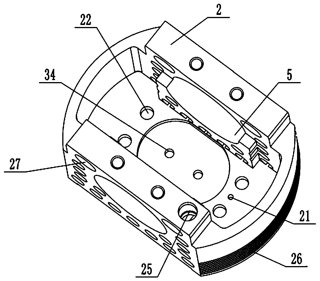
Embodiment 2

[0041] as attached Figure 6As shown, the difference between the present embodiment and the first embodiment is that the oil inlet hole 25 is opened on the piston pin seat 5 . This setting method is consistent with the oil inlet method of one of the integral pistons at present, which enters the oil chamber from the oil inlet hole 25 provided on the piston pin seat 5. Therefore, when replacing the piston in the existing cylinder, only It is only necessary to replace the original piston with the split-type steel-top and steel-skirt piston, and there is no need to slide other parts, which makes installation and use more convenient.

Embodiment 3

[0043] as attached Figure 7 As shown, the difference between the present embodiment and the first embodiment is that the oil inlet hole 25 is opened in the middle of the circular groove 32 on the oil guide cover 14 . The lubricating and cooling effects of this embodiment are the same as those of Embodiment 1, except that the flow direction of the lubricating oil is opposite. The oil inlet hole 25 enters in the annular round table 7, and enters in the oil chamber through eight through holes 12 of the annular round table 7, and finally, the lubricating oil flows back out from the oil discharge hole on the oil cover 4.


PUM


Abstract

The invention relates to the technical field of internal combustion engine pistons, and discloses a split-type steel top steel skirt piston. The split-type steel top steel skirt piston comprises a piston body provided with an oil inlet, wherein the piston body comprises a piston steel top and a piston steel skirt; an oil cavity and an oil cover are arranged on the piston steel top; a piston pin seat is arranged on the piston steel skirt; a first oil cavity, a second oil cavity and an annular circular table are arranged in the piston steel top; a first step, a second step, a first positioning hole and a through hole are arranged in the annular circular table; a discharge hole is formed in the oil cover; an oil guide cover is arranged on the first step; an oil drain hole is formed in the oilguide cover; a heat dissipation groove is formed in the top of the piston steel; the bottom of the piston steel skirt is provided with a circular boss and a second positioning hole; the bottom of thepiston steel skirt is provided with a separation hole; the top of the piston steel skirt is provided with an oil inlet hole; and the piston steel skirt is provided with a heat dissipation hole and anannular groove. According to the split-type steel top steel skirt piston, the problems in the prior art that the heat dissipation effect of a steel piston is poor and piston ring seal can fail when the steel piston operates due to the fact that the mass of the integral middle slotted steel piston is too heavy and the wall surface of the oil cavity is too thick are solved.

Description

technical field [0001] The invention relates to the technical field of internal combustion engine pistons, in particular to a split steel top and steel skirt piston. Background technique [0002] Piston, as a vital part of the internal combustion engine, bears alternating mechanical loads and thermal loads, and operates at high speed under high temperature and high pressure during the working process. The existing piston includes an integrally formed piston crown and piston skirt, and an oil chamber is arranged in the piston crown. When the piston works in the cylinder block of the internal combustion engine, the piston will continue to exert force against the cylinder wall under high temperature and high pressure, resulting in friction and heat, the lubricating oil in the oil chamber will flow out. On the one hand, it lubricates the piston to reduce the friction between the piston and the cylinder, and on the other hand, it cools the piston to avoid deformation caused by ex...

Claims


Application Information

Patent Timeline
Patent Type & Authority Applications(China)
IPC IPC(8): F02F3/00F02F3/02F01M9/00
CPCF01M9/00F02F3/0015F02F3/0092F02F3/02
Inventor 李进表
Owner 象山浦动机械科技有限公司
Learn More