Testing device for vertical anti-uplifting test of spiral ground anchor and operation method of testing device

A technology of spiral ground anchor and testing device, which is applied in the testing of basic structures, construction, and basic structure engineering, etc., can solve the problems of inability to design for engineering, large error of test results, strong randomness of results, etc., so as to solve the problems of blindness and The effect of randomness, simple equipment, easy processing and transportation

CN106836322AActive Publication Date: 2017-06-13TONGJI UNIV
2 Cites 0 Cited by

Patent Information

Authority / Receiving Office
CN · China
Current Assignee / Owner
Publication Date
2017-06-13

Smart Images

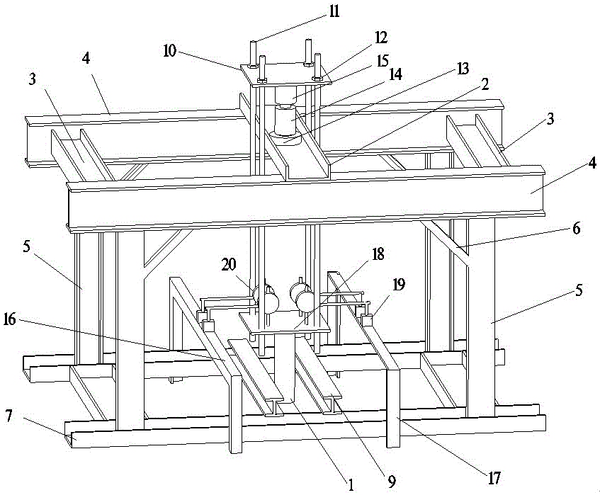
  • Figure 1
    Figure 1
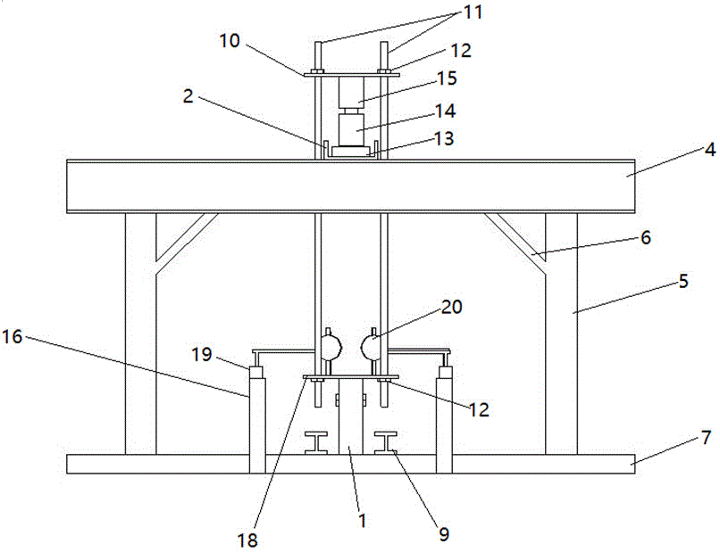
  • Figure 2
    Figure 2
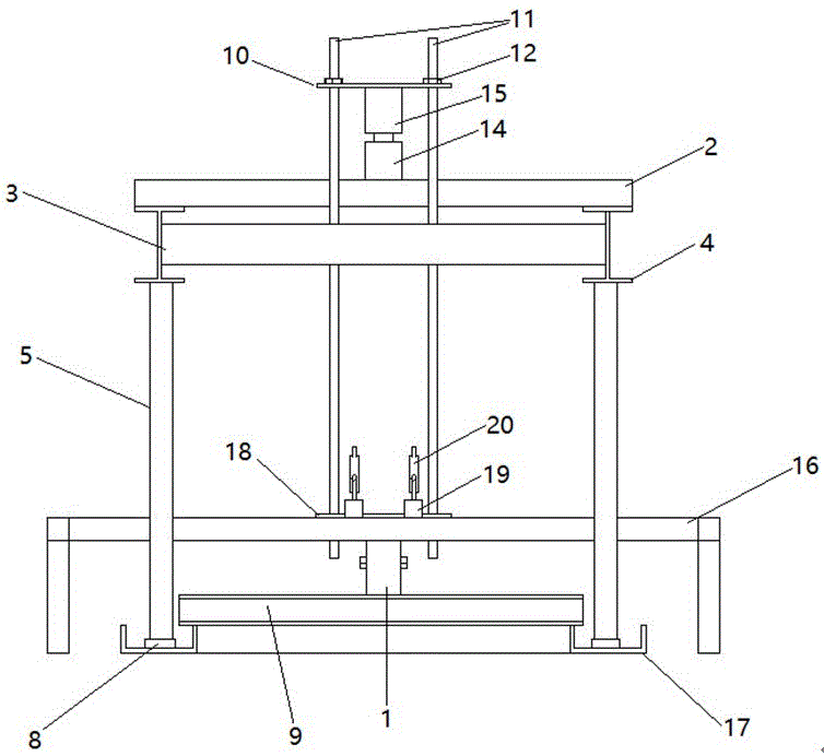
  • Figure 3
    Figure 3
Patent Text Reader

Abstract

The invention relates to a testing device and testing method for a vertical anti-uplifting test of a spiral ground anchor. The testing device is composed of a counterforce system, a loading system and a measuring system, wherein the counterforce system is commonly composed of a central counterforce beam, a bottom supporting beam, a force transmission beam column and a bracing piece, and a positioning beam, and is used for bearing the counterforce in the loading process; the loading system is composed of a jack and a cushion block, a supporting top plate, a pile head connecting piece and a continuous screw rod, and is matched with the counterforce system to apply vertical uplifting load to a spiral ground anchor pile head; the measuring system is composed of a pressure sensor, a displacement meter and a standard beam and is used for determining the size of the applied load and pile head displacement of the spiral ground anchor under each grade of load effect. The testing method for the vertical anti-uplifting test of the spiral ground anchor comprises the following steps: positioning a counterforce bracket based on the testing device for the vertical anti-uplifting test; then applying an uplifting force to the spiral ground anchor by utilizing the continuous screw rod, the supporting top plate and the pile head connecting piece; bearing the uplifting counter forceby the counterforce bracket to obtain pile head displacement of the spiral ground anchor under each grade of the load effect; and judging an anti-uplifting bearing force of the spiral ground anchor through a displacement loading curve.
Need to check novelty before this filing date? Find Prior Art

Description

technical field

[0001] The invention belongs to the technical field of geotechnical engineering pile foundations, and in particular relates to a test device suitable for a vertical pull-out test of a spiral ground anchor and an operation method thereof. Background technique

[0002] The spiral ground anchor consists of a steel pipe pile body and a steel spiral piece welded to the pile body. It is a new type of pile foundation. The pile length is usually between 1.2m and 1.8m, and it is a miniature short pile. During piling construction, the characteristics of the spiral blades are used to screw the steel piles into the ground as a force-bearing foundation. At present, it is mainly used for the basic structure of photovoltaic solar power generation supports. The main stress form of the spiral ground anchor is vertical uplift resistance. In actual engineering, especially in areas with large wind loads, the foundation will shake or be pulled out under a large vertical uplift lo...

Examples

Embodiment

[0027] Example 1: If Figure 1~5 As shown, the test device above the ground pile head 1 of the spiral ground anchor consists of a central reaction beam 2 of the reaction support, a support beam 3, a force transmission beam 4, a force transmission column 5, a support brace 6, a bottom support beam 7, a fixed anchor Nail fixing hole 8, positioning beam 9, supporting top plate 10, continuous threaded rod 11, fixing nut 12, pressure sensor 13, jack 14, supporting pad 15, reference beam 16, reference beam column foot 17, top of pile head connector Square steel plate 18, displacement meter table seat 19, displacement meter 20, support beam 21 at the bottom of the support, four corners of perforation 22 of pile head connector, pile head connector steel cylinder 23 and pile head connection bolt 24 form.

[0028] The structure of the reaction force system is as follows: two force transmission beams 4 and two support beams 3 are connected to form the upper support structure, the central...