LED lamp

A technology of LED lamps and LED light sources, applied in lighting devices, cooling/heating devices of lighting devices, light sources, etc., can solve the problems of cumbersome and complicated assembly procedures, scrapping of the whole lamp, difficult disassembly, etc., and achieve ideal heat dissipation effect and high heat conduction efficiency High, easy and fast installation and disassembly

Inactive Publication Date: 2017-07-21
余胜荣
View PDF8 Cites 0 Cited by
  • Summary
  • Abstract
  • Description
  • Claims
  • Application Information

AI Technical Summary

Problems solved by technology

LED lamps generally include a lamp body structure and an LED light source structure arranged on the lamp body structure. The lamp body structure and the LED light source structure are an integral structure. Once a certain part is damaged, the entire lamp will be scrapped, which is not energy-saving and environmentally friendly. The assembly process of the existing LED lamps is cumbersome and complicated, and it is difficult to disassemble after assembly, which is not conducive to the later maintenance and replacement work
In addition, the heat dissipation efficiency of LED lamps, especially high-power LED lamps, is very important, which directly affects the service life of the whole lamp. However, the heat conduction and heat dissipation efficiency of existing LED lamps is average, and there is a problem of unsatisfactory heat dissipation effect.

Method used


Image

  • LED lamp
  • LED lamp
  • LED lamp

Examples


Embodiment Construction

[0019] It should be understood that the specific embodiments described here are only used to explain the present invention, not to limit the present invention.

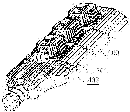
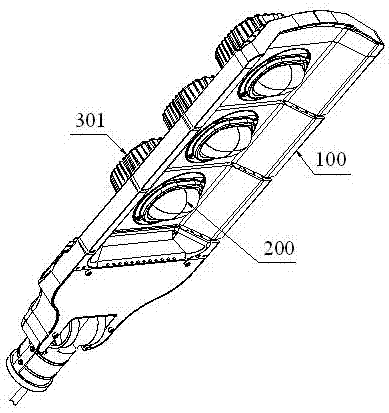
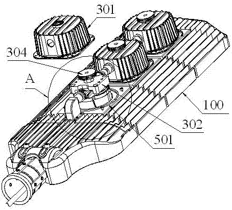
[0020] refer to Figure 1 to Figure 6 , an embodiment of an LED lamp according to the present invention is proposed, including several lamp body structures 100, an installation cavity seat provided on the lamp body structure 100, and an LED light source that can pass through the lamp body structure 100 and be installed into the installation cavity seat The structure 200 is a driving device arranged on the lamp body structure 100 and electrically connected to the LED light source structure 200 .

[0021] The upper end of the LED light source structure 200 is provided with a thermally conductive mounting plate 201, and the upper end of the thermally conductive mounting plate 201 is provided with two pin holders 202, and each pin holder 202 is provided with two conductive pins 203, and the thermally conductive mounting p...


PUM


Abstract

The present invention discloses an LED lamp. The LED lamp comprises a plurality of lamp body structures, installation cavity bases disposed on the lamp body structures, LED light source structures which can penetrate through the lamp body structures and be installed into the installation cavity bases, and a drive device disposed on the lamp body structures and electrically connected with the LED light source structures. A heat conduction installation plate is disposed on the upper end of each LED light source structure, two contact pin seats are disposed on the upper end of each heat conduction installation structure, each contact pin seat is provided with two conductive contact pins, and a screw hole post stretches upwards from the upper end of the heat conduction installation plate. Each installation cavity base comprises a cavity base housing installed on the corresponding lamp body structure, an installation seat disposed inside the cavity base housing, a conductive socket structure which is disposed inside the installation seat and can allow the conductive contact pins to insert in for electrification, and a screw structure which can penetrate through the cavity base housing and then be screwed into the screw hole so as to enable the conductive contact pins and the conductive socket structure to closely contact with each other and enable the cavity base housing and the LED light source structure to be in close fit at the same time for heat conduction and dissipation so as to ultimately realize an electric heating synchronous effect.

Description

technical field [0001] The invention relates to the technical field of lamps, in particular to an LED lamp. Background technique [0002] LED lamps are widely used due to the advantages of energy saving, low carbon, long life, good color rendering, high luminous efficiency, good luminous effect, and fast response. LED lamps generally include a lamp body structure and an LED light source structure arranged on the lamp body structure. The lamp body structure and the LED light source structure are an integral structure. Once a certain part is damaged, the entire lamp will be scrapped, which is not energy-saving and environmentally friendly. The assembly process of the existing LED lamps is complicated and complicated, and it is difficult to disassemble after assembly, which is not conducive to the maintenance and replacement work in the later period. In addition, the heat dissipation efficiency of LED lamps, especially high-power LED lamps, is very important, which directly ...

Claims


Application Information

Patent Timeline
Patent Type & Authority Applications(China)
IPC IPC(8): F21K9/20F21V19/00F21V17/12F21V23/06F21V29/507F21Y115/10
CPCF21V17/12F21V19/0025F21V23/06F21V29/507
Inventor 余胜荣
Owner 余胜荣
Why Eureka
Try Eureka