Tower light condensing system light condensing reflecting mirror arrangement structure and tracking method thereof

A concentrating system and arranging structure technology, applied in the direction of control using feedback, etc., can solve the problems of increasing the cost of tracking mechanism, complex control signals, and different rotation angles

Inactive Publication Date: 2017-08-11
BEIJING TERASOLAR PHOTOTHERMAL TECH CO LTD
View PDF5 Cites 5 Cited by
  • Summary
  • Abstract
  • Description
  • Claims
  • Application Information

AI Technical Summary

Problems solved by technology

[0004] In general, the tracking driving mechanism of the tower heliostat is composed of a driving device rotating around the vertical axis and a driving device rotating around the horizontal axis. Since the positions of each heliostat in the mirror field are different, Therefore, the rotation angle of the two-axis driving device of each heliostat is different, and the rotation angle of the two axes of each heliostat is related to the azimuth and altitude angle of the sun, so the control signal is quite complicated. It is necessary to perform complex calculations and send different drive control signals to the two axes of thousands of heliostats at any time
In addition, these heliostat tracking mechanisms need to have high tracking accuracy to ensure the accuracy of the heliostat's focusing angle, and also need to have strong structural strength to ensure that the shape and angle of the heliostat lens remain unchanged in a windy environment and not to be compromised, this dual requirement greatly increases the cost of the tracking agency

Method used


Image

  • Tower light condensing system light condensing reflecting mirror arrangement structure and tracking method thereof
  • Tower light condensing system light condensing reflecting mirror arrangement structure and tracking method thereof
  • Tower light condensing system light condensing reflecting mirror arrangement structure and tracking method thereof

Examples


Embodiment 1

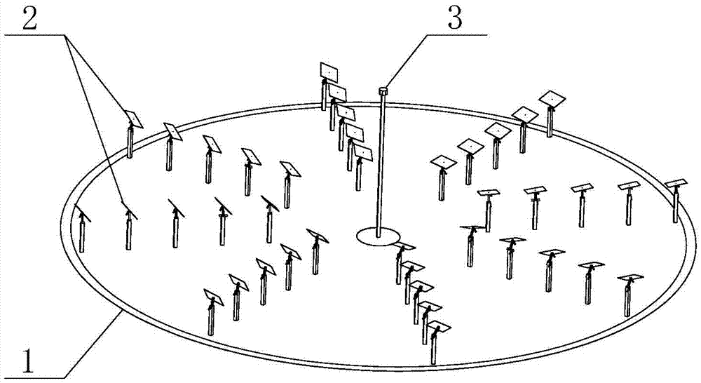
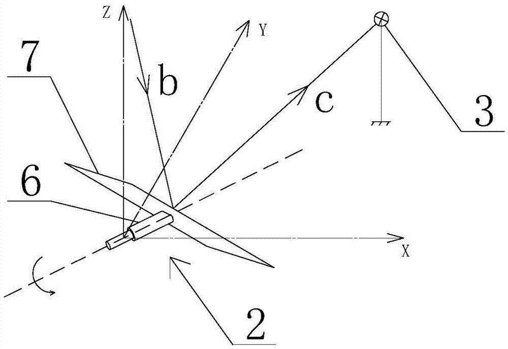
[0062] Such as figure 1 , 2 As shown, the reflector arrangement structure in the tower power station provided by this embodiment includes a rotating device 1 arranged horizontally around the receiving device 3 and a plurality of reflecting members 2 arranged on the rotating device 1; and the reflecting members 2 are arranged in Driven by the rotating device 1, it rotates and moves in the horizontal plane with the vertical line of the center point of the receiving device 3 as the axis, so that the reflecting member 1 uniformly tracks the azimuth of the sun; the reflecting member 2 includes a rotating shaft 6 And the reflector 7 affixed to the rotating shaft 6, the rotating shaft 6 is arranged obliquely at a fixed angle with the horizontal plane and the vertical plane; wherein, the rotating shaft 6 drives the reflecting mirror 7 to rotate, so that the reflecting mirror 7 Tracking the sun's altitude angle and reflecting the sun's incident light to the receiving range of the rece...

Embodiment 2

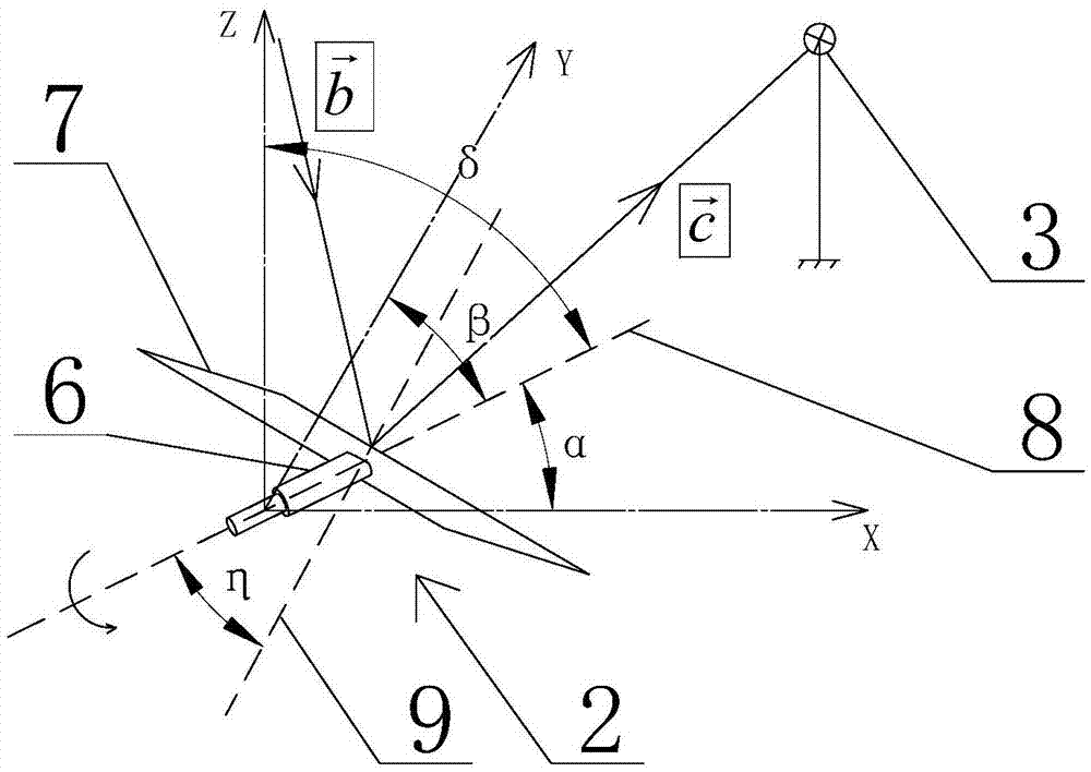
[0067] Such as image 3 As shown, the arrangement structure of the concentrating mirrors of the tower concentrating system provided in this embodiment includes a rotating device arranged horizontally around the receiving device 3 and a plurality of reflecting members 2 arranged on the rotating device; and the reflecting Driven by the rotating device, the member 2 rotates and moves in the horizontal plane with the vertical line of the center point of the receiving device 3 as the axis, so that all the reflecting members 2 uniformly track the azimuth of the sun; the reflecting member 2 includes A rotating shaft 6 and a reflector 7 affixed to the rotating shaft 6, the rotating shaft 6 is arranged obliquely at a fixed angle with the horizontal plane and the vertical plane; wherein, the rotating shaft 6 drives the reflecting mirror 7 to rotate, so that the The reflector 7 tracks the sun's altitude angle and reflects and gathers the incident light from the sun to the same spot on th...

Embodiment 3

[0101] Such as Figures 4 to 6As shown, the arrangement structure of the concentrating mirrors of the tower concentrating system provided in this embodiment includes a rotating device arranged horizontally around the receiving device 3 and a plurality of reflecting members arranged on the rotating device; and the reflecting member Driven by the rotating device, it rotates and moves in the horizontal plane with the vertical line of the center point of the receiving device 3 as the axis, so that all the reflecting members uniformly track the azimuth of the sun; the reflecting member includes a rotating shaft and The reflector fixed to the rotating shaft is arranged obliquely at a fixed angle to the horizontal plane and the vertical plane; wherein, the rotating shaft drives the reflecting mirror to rotate, so that the reflecting mirror tracks the sun's altitude angle and makes the sun incident The light is reflected into the receiving range of the receiving device 3 .

[0102] W...


PUM


Abstract

The invention provides a tower light condensing system light condensing reflecting mirror arrangement structure and a tracking method thereof. The tower light condensing system light condensing reflecting mirror arrangement structure comprises a rotating device which is horizontally arranged around a receiving device and multiple reflecting components which are arranged on the rotating device, wherein the reflecting components move in a rotating way in the horizontal plane under driving of the rotating device with the vertical line of the central point of the receiving device acting as the axis so that all the reflecting components are enabled to track the azimuth of the sun in a unified way. Each reflecting component comprises a rotating shaft and a reflecting mirror fixedly connected with the rotating shaft, and the rotating shaft is arranged in an inclined way at a fixed angle with the horizontal plane and the vertical plane, wherein the rotating shaft drives the reflecting mirror to rotate so that the reflecting mirror is enabled to track the solar elevation angle and reflect the incident light of the sun to the receiving range of the receiving device. The complexity of a reflecting mirror tracking mechanism can be greatly simplified, the reliability can be enhanced and the cost can be reduced.

Description

technical field [0001] The invention relates to an arrangement structure of a light-condensing reflector, in particular to an arrangement structure of a light-condensing reflector of a tower-type light-condensing system and a tracking method thereof. Background technique [0002] The solar tower concentrator power station is generally composed of heliostats, high towers, receiving devices located on the high towers, heat transfer and heat storage systems, and generators. Due to its high concentration multiples, the receiving device can obtain higher The heat collection temperature is widely used. [0003] Among them, the arrangement structure of the heliostats is generally to install multiple heliostats on a large-scale site, and the multiple heliostats are arranged to form a heliostat mirror field. Since the positions of the heliostats in the mirror field are different , and the spatial position of the sun moves and changes in the two dimensions of altitude and azimuth. In...

Claims


Application Information

Patent Timeline
Patent Type & Authority Applications(China)
IPC IPC(8): G05D3/12
CPCG05D3/12
Inventor 刘阳李维
Owner BEIJING TERASOLAR PHOTOTHERMAL TECH CO LTD
Why Eureka
Try Eureka