
A holographic display device for display cabinets based on optical interference and diffraction

An optical interference and display device technology, applied in optics, projection devices, instruments, etc., can solve problems such as difficult operation, unfavorable promotion and application of optical holographic imaging technology, flexibility of use and practical constraints, etc., to achieve flexible and convenient use , improve flexibility, simple structure

Inactive Publication Date: 2019-07-30
辛小英
View PDF6 Cites 0 Cited by
  • Summary
  • Abstract
  • Description
  • Claims
  • Application Information

AI Technical Summary

Problems solved by technology

[0002] With the rapid development of electronic information technology and optical technology, optical holographic imaging technology has been widely used in the display of product entity information, video information, etc., but found in actual use, the current optical holographic imaging When the device is in use, it often uses projection equipment to directly holographically project the displayed information. Although it can meet the needs of use, it cannot flexibly adjust the displayed information, and it also requires a lot of related work before displaying the displayed information. As a result, the current optical holographic imaging equipment is relatively poor in flexibility and difficult to operate, which is not conducive to the promotion and application of optical holographic imaging technology. In addition, the current optical holographic imaging device is in use However, it is not possible to flexibly meet the needs of random display of multiple different item information according to the display needs, so the flexibility and practicability of the use are further restricted. Therefore, in view of this situation, it is urgent to develop an inventive optical holographic imaging device to meet the needs of practical use

Method used


Image

  • A holographic display device for display cabinets based on optical interference and diffraction

Examples


Embodiment Construction

[0014] In order to make the technical means realized by the present invention, creation feature, purpose and effect be easy to understand, the following

[0015] The present invention will be further elaborated in combination with specific embodiments.

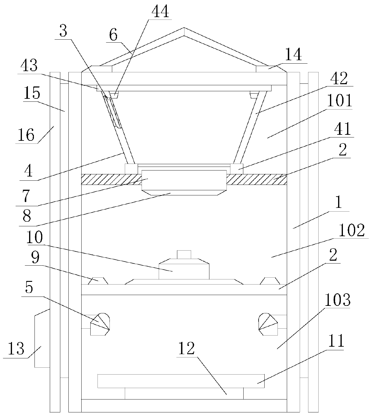
[0016] Such as figure 1 The holographic display device of a display cabinet based on optical interference and diffraction includes a carrier frame 1, a partition plate 2, a coated glass 3, a projection frame 4, a camera 5, an LED display 6, a projection imaging glass 7, and a holographic projection film 8 , lighting lamp 9, projector 10, bearing platform 11, turntable mechanism 12 and control system 13, bearing frame 1 is a frame structure with a rectangular cross section, and there are two partitions 2, embedded in the bearing frame 1, and connected with the bearing frame The frame 1 is coaxially distributed, and the partition plate 2 divides the carrier 1 from top to bottom into a holographic imaging cavity 101, a projectio...


PUM


Abstract

The invention relates to a display cabinet holographic display device based on optical interference and diffraction, which includes a carrier frame, a partition, a coated glass, a projection frame, a camera, an LED display, a projection imaging glass, a holographic projection film, a lighting lamp, a projector, a carrier Platform, turntable mechanism and control system, the partition divides the carrier frame from top to bottom into a holographic imaging cavity, a projection cavity and a carrier cavity, the carrier platform is embedded in the bottom of the carrier cavity through the turntable mechanism, cameras are evenly distributed around the carrier platform, and the projector is installed At the bottom of the projection chamber, lighting lamps are evenly distributed around the optical axis of the projector. The projection imaging glass is embedded in the partition between the projection chamber and the contact surface of the bearing chamber. The coated glass is connected to each other through the projection frame, and the LED display is embedded in the upper end of the holographic imaging chamber. On the one hand, the present invention can effectively meet the needs of the optical holographic imaging display operation for the required display information, and on the other hand, it can flexibly display the required display items from multiple angles in the process of displaying the holographic information.

Description

technical field [0001] The invention relates to a holographic display device, in particular to a display cabinet holographic display device based on optical interference and diffraction. Background technique [0002] With the rapid development of electronic information technology and optical technology, optical holographic imaging technology has been widely used in the display of product entity information, video information, etc., but found in actual use, the current optical holographic imaging When the device is in use, the displayed information is often holographically projected directly through the projection equipment. Although it can meet the needs of use, it cannot flexibly adjust the displayed information, and it also requires a lot of related work before displaying the displayed information. As a result, the current optical holographic imaging equipment is relatively poor in flexibility and relatively difficult to operate, which is not conducive to the promotion and...

Claims


Application Information

Patent Timeline
Patent Type & Authority Patents(China)
IPC IPC(8): G03H1/22G03B21/54G03B35/00
CPCG03B21/54G03B35/00G03H1/22
Inventor 辛小英
Owner 辛小英
Learn More