air conditioner indoor unit

A technology for indoor units and enclosures of air conditioners, which is applied in air conditioning systems, mechanical equipment, space heating and ventilation, etc., and can solve the problem of intermittent air supply at the outlet, affecting user comfort experience, increasing manufacturing costs and power consumption, etc. problems, to achieve a good user experience, avoid direct blowing to the human body, and reduce the effect of restrictions

Active Publication Date: 2020-08-25
QINGDAO HAIER AIR CONDITIONER GENERAL CORP LTD +2
View PDF5 Cites 0 Cited by
  • Summary
  • Abstract
  • Description
  • Claims
  • Application Information

AI Technical Summary

Problems solved by technology

That is to say, this kind of air-conditioning indoor unit not only does not really expand its air supply range, but also causes a substantial increase in manufacturing cost and power consumption due to the addition of two air outlets and the addition of two fans.
To take a step back, even if the installation position of the indoor unit of the air conditioner is not considered, the air sent by the multiple air outlets of the indoor unit of the air conditioner is directly blown out in two opposite directions or directions perpendicular to each other. Intermittent and discontinuous, resulting in uneven indoor temperature, which seriously affects the user's comfort experience

Method used


Image

  • air conditioner indoor unit
  • air conditioner indoor unit
  • air conditioner indoor unit

Examples


Embodiment Construction

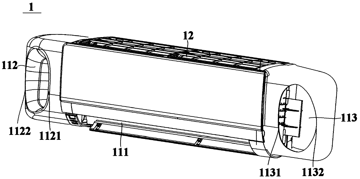
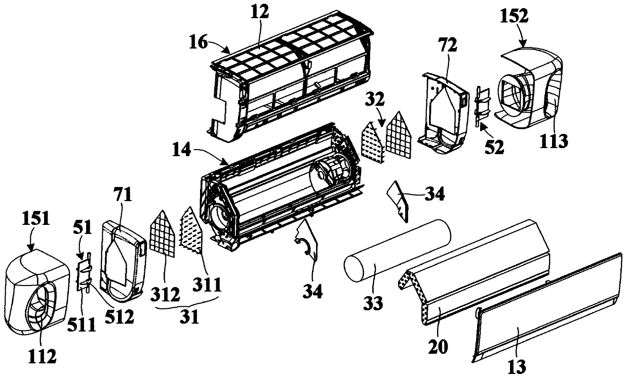
[0042] An embodiment of the present invention provides an air conditioner indoor unit, figure 1 is a schematic structural diagram of an air conditioner indoor unit according to an embodiment of the present invention, figure 2 is a schematic exploded view of an air conditioner indoor unit according to an embodiment of the present invention. see figure 1 and figure 2 , the air conditioner indoor unit 1 of the embodiment of the present invention includes a casing, a heat exchange device 20 , a cross-flow fan 33 , a first ion wind generating device 31 and a second ion wind generating device 32 .

[0043]The casing has at least one air inlet, a lower air outlet 111 located at the lower part of the casing, and a first side air outlet 112 and a second side air outlet 113 respectively located on both sides of the casing and facing the lateral front of the casing . Specifically, the wind sent through the first side air outlet 112 and the second side air outlet 113 is blown toward...


PUM


Abstract

The invention relates to an air conditioner indoor unit which comprises a unit shell, a heat exchange device, a cross flow draught fan, a first ion wind generation device and a second ion wind generation device. The unit shell is provided with at least one air inlet, a lower air outlet located in the lower portion of the unit shell, a first lateral air outlet and a second lateral air outlet, wherein the first lateral air outlet and the second lateral air outlet are located in the two sides of the unit shell correspondingly and face the lateral front side of the unit shell. The heat exchange device is arranged in the unit shell and is configured to conduct heat exchange with air flowing through the heat exchange device. The cross flow draught fan is arranged on a flowing path from the heat exchange device to the lower air outlet in the unit shell so that air obtained after heat exchange of the heat exchange device can flow towards the lower air outlet. The first ion wind generation device and the second ion wind generation device are arranged on a flowing path between the heat exchange device and the first lateral air outlet in the unit shell and a flowing path between the heat exchange device and the second lateral air outlet in the unit shell correspondingly so that air obtained after heat exchange of the heat exchange device can flow towards the first lateral air outlet and the second lateral air outlet. Thus, noise of the air conditioner indoor unit during running is lowered, and the air supply range of the air conditioner indoor unit is enlarged.

Description

technical field [0001] The invention relates to air-conditioning technology, in particular to an air-conditioning indoor unit. Background technique [0002] At present, traditional wall-mounted air-conditioning indoor units mostly use downward air outlet, and a guide plate is usually provided at the air outlet to adjust the air outlet direction of the air outlet by swinging the guide plate up and down or left and right. However, the adjustment range of this method is limited, and it is difficult to realize the air supply requirements in a wide range. Even if the fluid is raised or blown sideways by some unconventional means on the basis of the traditional wall-mounted air conditioner indoor unit, the loss of wind speed and wind pressure is relatively large, resulting in high power consumption and high noise of the air conditioner indoor unit. [0003] Some air-conditioning indoor units in the prior art are respectively provided with an air outlet at its bottom and left and ...

Claims


Application Information

Patent Timeline
Patent Type & Authority Patents(China)
IPC IPC(8): F24F1/0014F24F1/0025F24F1/0063F24F1/0076F24F13/02F24F13/20F24F13/24F24F13/14
CPCF24F1/0003F24F1/0025F24F3/16F24F13/02F24F13/20F24F13/24F24F2013/247F24F8/30
Inventor 李健王永涛关婷婷闫宝升
Owner QINGDAO HAIER AIR CONDITIONER GENERAL CORP LTD
Why Eureka
Try Eureka