
Wheel lifting and folding device
A folding device and wheel technology, which is applied to motor vehicles, amphibious vehicles, vehicle parts, etc., can solve the problems of slowing down the speed, increasing resistance in water, and affecting the overall performance of the vehicle, and achieves simplicity, compactness, easy maintenance, and compact structure Effect
- Summary
- Abstract
- Description
- Claims
- Application Information
AI Technical Summary
Problems solved by technology
Method used
Image

Examples
Embodiment Construction
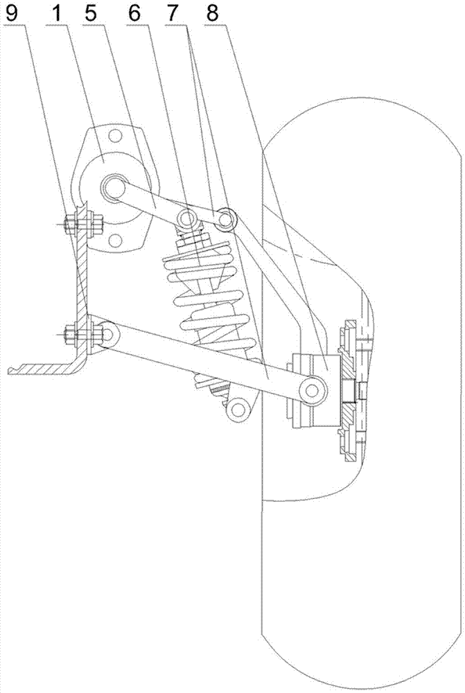
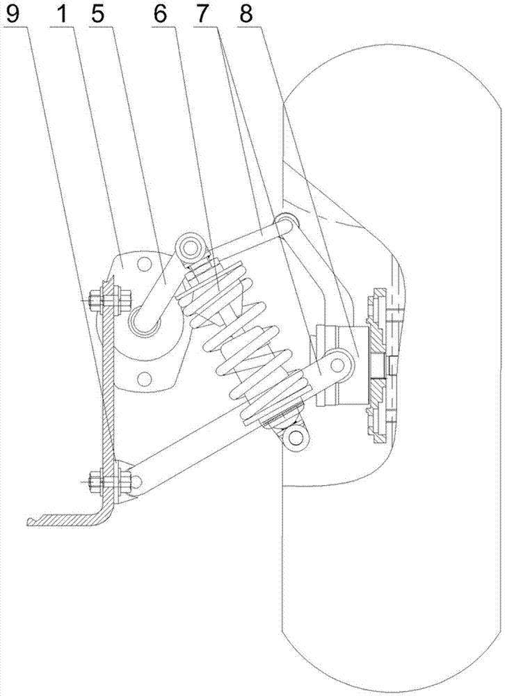
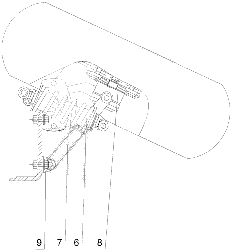
[0014] Depend on figure 1 , figure 2 , image 3 and Figure 4 It can be seen that the present invention includes a hydraulic motor 1, a rotary switch 2, an electric control valve A 3, an electric control valve B 4, a rotating arm 5, a shock absorber 6, a rocker arm 7, a wheel hub assembly 8, a rocker arm mounting seat 9 and a hydraulic Motor mount 10.
[0015] Depend on figure 1 and figure 2 It can be seen that hydraulic motor 1, rotary switch 2, electric control valve A 3, electric control valve B 4 are ad hoc in order to lift the wheel rapidly and make it leave the water surface, and hydraulic motor 1 is fixed on the motor mounting seat 10.
[0016] Depend on figure 1 and figure 2 It is also known that through the rotary switch 2, the electric control valve A 3 and the electric control valve B 4, the inflow and outflow directions of the hydraulic oil can be changed rapidly, so that the hydraulic motor 1 can rotate forward or reversely.
[0017] Depend on figure 1...
PUM
 Abstract
Description
Claims
Application Information