
Suction cup type film-taking apparatus
A suction cup type and outer tube technology, which is applied in the field of medical devices, can solve the problem of inhalation of liquid medicine into the gas cylinder, etc., and achieve the effect of fast tablet taking and unloading, simple structure and convenient use
- Summary
- Abstract
- Description
- Claims
- Application Information
AI Technical Summary
Problems solved by technology
Method used
Image

Examples
Embodiment Construction
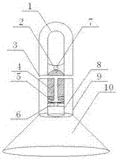
[0016] The present invention will be described below in conjunction with the accompanying drawings. Such as figure 1 as shown, figure 1 It is a structural schematic diagram of the present invention.
[0017] The present invention includes an outer sleeve 9 and a negative pressure lifting sheet cover 10 fixed on the bottom of the outer sleeve 9, wherein a pressure relief hole 3 is provided in the middle of the outer sleeve 9, and a pressure relief valve 4 and an inner sleeve are arranged inside the outer sleeve 9 8. The bottom of the inner casing 8 is provided with a spring table 6, and the two sides of the spring table 6 are provided with a return spring 5. The upper part of the return spring 5 is provided with a pressure relief valve 4. The upper part of the pressure relief valve 4 is airtight, and the pressure relief valve 4 The upper part of the pressure relief valve 7 is provided with a pressure relief ball 7, the upper part of the pressure relief ball 7 is provided with...
PUM
 Abstract
Description
Claims
Application Information