
A circular cutting blade and cutting tool with accurate positioning structure
A cutting insert, accurate positioning technology, applied in the field of cutting processing, can solve the problems of cutting vibration, lack of concentricity, low cutting efficiency, etc., and achieve the effect of improving clamping rigidity
- Summary
- Abstract
- Description
- Claims
- Application Information
AI Technical Summary
Problems solved by technology
Method used
Image

Examples
Embodiment 1
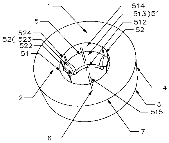
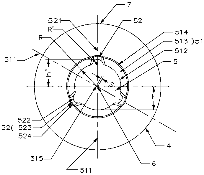
[0035] Such as Figures 1 to 4 As shown, the circular cutting insert with an accurate positioning structure in this embodiment includes a circular blade body 1 composed of an upper surface 2, a lower surface 3, and a side surface 4 connecting the upper surface 2 and the lower surface 3. The blade body 1 There is a central hole 5 that runs through the upper surface 2 and the lower surface 3. The blade body 1 is symmetrical about the central axis 6 of the central hole 5. The upper surface 2 intersects with the side 4 to form a cutting edge 7. The inner surface of the central hole 5 is provided with at least one There is an arc-shaped groove 51 that can cooperate with the surface of the fastening screw 11 for fixing the circular cutting blade.
[0036]In this embodiment, the inner surface of the center hole 5 is provided with three arc-shaped grooves 51, and the three arc-shaped grooves 51 are evenly arranged along the inner surface of the center hole 5, and the three arc-shaped ...
Embodiment 2
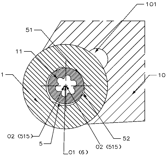
[0045] Such as Figure 5 As shown, the cutting tool of this embodiment includes a cutter body 10 and a fastening screw 11, the cutter body 10 is a square cutter bar, and a cutter groove 101 is provided on the cutter body 10, and the cutting tool also includes a circle in embodiment 1. Shaped cutting blades, the number of circular cutting blades corresponds to the number of sipe grooves 101, and the present embodiment is set to one. The circular cutting blade is installed in the sipe 101 , and the fastening screw 11 is passed through the central hole 5 , concentrically contacts with at least one arc-shaped groove 51 and presses the circular cutting blade into the sipe 101 .
[0046] In this embodiment, the positioning and installation process of the circular cutting insert is as described in Embodiment 1. In this embodiment, in the final positioning, the arc-shaped groove 51 and the fastening screw 11 form three sets of continuous arc-shaped over-positioning clamping.
[0047...
Embodiment 3
[0051] Such as Figures 6 to 8 As shown, the circular cutting insert of this embodiment is basically the same as that of Embodiment 1, the difference is that:
[0052] In this embodiment, there are four arc-shaped grooves 51, four corner grooves 52, and each corner groove 52 is arranged between two adjacent arc-shaped grooves 51. Among the arc-shaped grooves 51 , two of them are symmetrical about the central axis 6 , and the other two are also symmetrical about the central axis 6 . Similarly, the four corner grooves 52 also have the same symmetrical structure.
[0053] In this embodiment, the center-to-center distance between two arc-shaped grooves 51 (located on the same straight line) that are symmetrical about the center of the central axis 6 is 2S.
[0054] In this embodiment, the groove symmetry plane 511 and the corner groove symmetry plane 521 are perpendicular to each other.
[0055] In this embodiment, the positioning and installation process of the circular cutting...
PUM
 Abstract
Description
Claims
Application Information