Traffic control device for road bridge

A road bridge and line restriction technology, applied in the directions of roads, roads, road signs, etc., can solve the problems of inconvenient use of road limit devices for highway bridges, troublesome handling of guardrails, and large size of guardrails, so as to improve the effect, convenience, and convenience of road restriction. high effect

Inactive Publication Date: 2018-01-26
诗莎兰妮(青岛)电子商务有限公司
View PDF0 Cites 0 Cited by
  • Summary
  • Abstract
  • Description
  • Claims
  • Application Information

AI Technical Summary

Problems solved by technology

[0002] With the continuous development of social economy and the continuous improvement of people's living standards, more and more families have private cars; due to the increase of vehicles, in urban roads, it is often necessary to use guardrails to separate the two sides of the road to ensure The traffic is smooth; especially in harsh environments, such as rainy and snowy weather, the road transport management department usually needs to close the road bridge; therefore, the staff needs to place guardrails to prevent vehicles from passing, because the guardrails are large in size and mostly made of steel or cement, which brings great trouble to the handling of guardrails, and at the same time, the existing road and bridge traffic restriction devices are extremely inconvenient to use

Method used


Image

  • Traffic control device for road bridge
  • Traffic control device for road bridge
  • Traffic control device for road bridge

Examples


Embodiment Construction

[0016] The following will clearly and completely describe the technical solutions in the embodiments of the present invention with reference to the accompanying drawings in the embodiments of the present invention. Obviously, the described embodiments are only some, not all, embodiments of the present invention. Based on the embodiments of the present invention, all other embodiments obtained by persons of ordinary skill in the art without making creative efforts belong to the protection scope of the present invention.

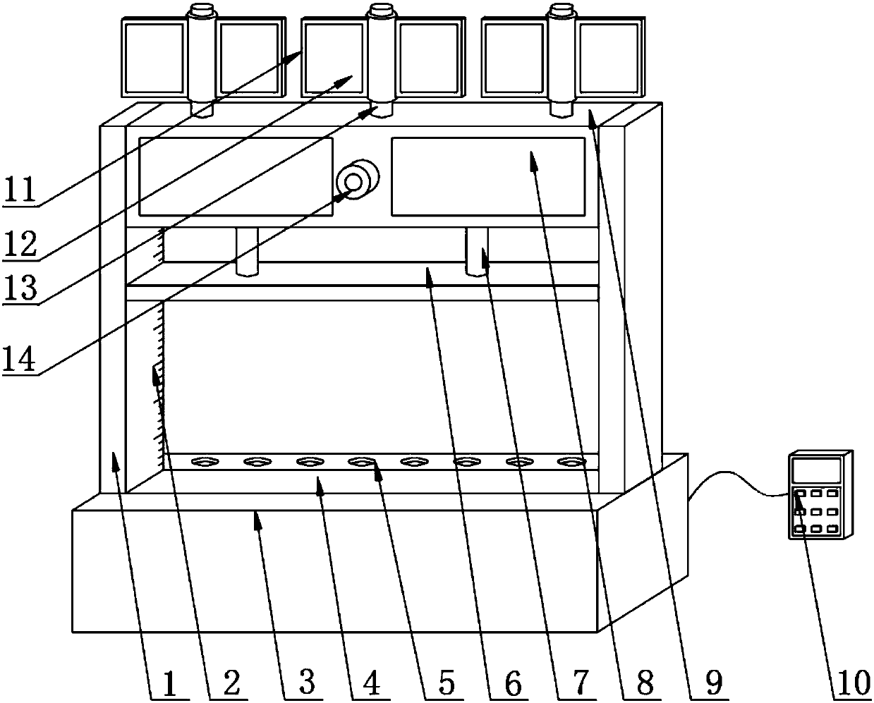
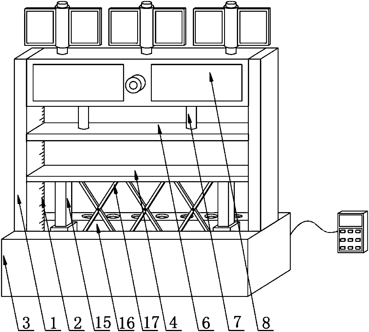
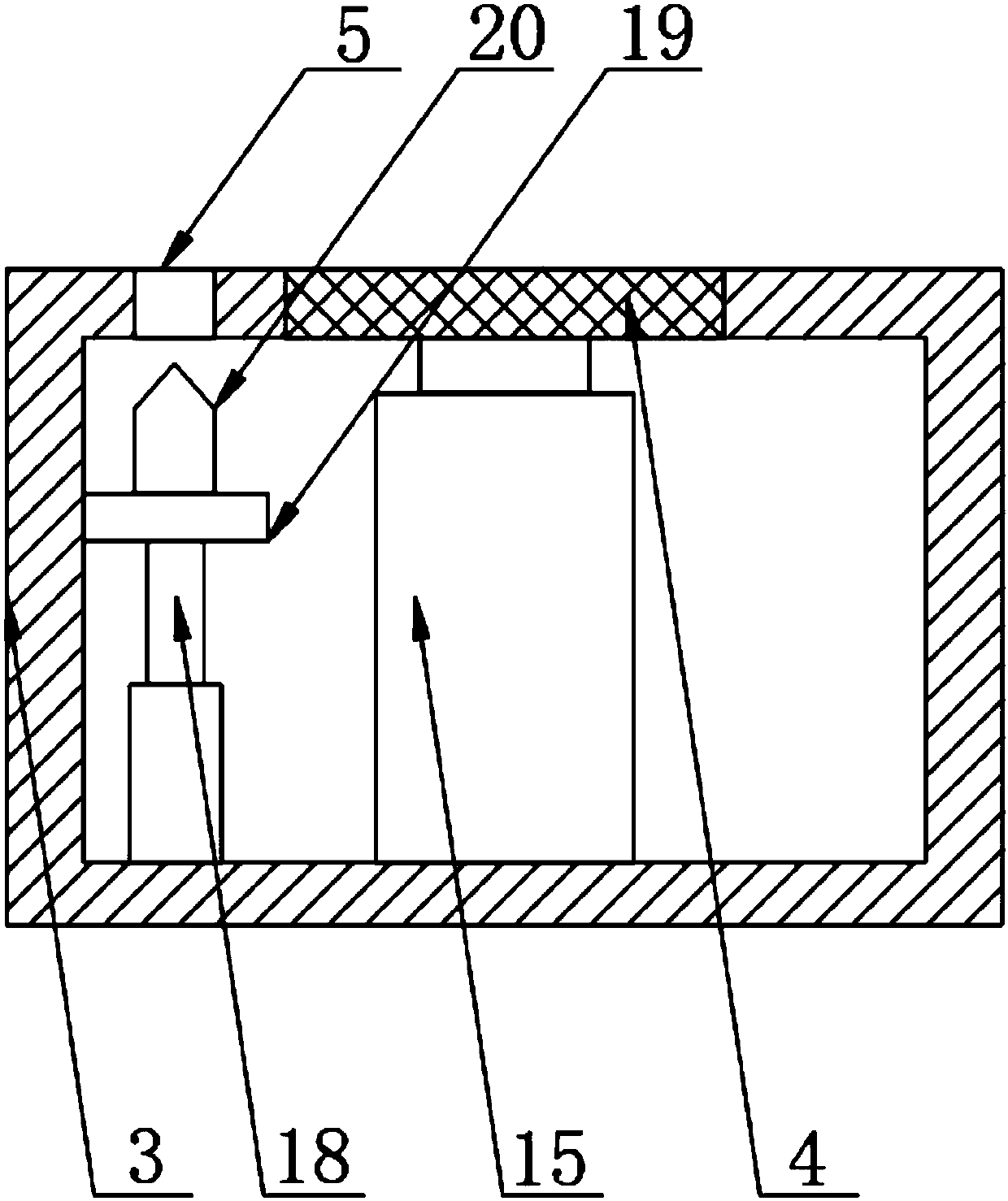
[0017] see Figure 1-4 , the present invention provides a technical solution: a road bridge restriction device, including a support beam 1, a scale bar 2, a base 3, a top plate 4, a through hole 5, a pressure plate 6, a first electric push rod 7, a display screen 8, and a beam 9. Control board 10, fan 11, solar panel 12, rotating shaft 13, camera 14, second electric push rod 15, groove 16, retractable guardrail 17, third electric push rod 18, fixing plate 19, ...


PUM


Abstract

The invention discloses a traffic control device for a road bridge. The traffic control device comprises support beams, graduated bars, a base, a pushing plate, through holes, a pressing plate, firstelectric push rods, display screens, a crossbeam, a control panel, fans, solar panels, rotary shafts, a camera, second electric push rods, a groove, a telescopic guardrail, third electric push rods, fixing plates, vertical nails, a storage battery and a wind-driven generator and is characterized in that the control panel is connected to one side of the base through a wire, the groove is formed inthe center of the top of the base, the pushing plate is mounted in the groove, the two corresponding sides of the bottom of the pushing plate are connected with the bottom inner wall of the base through the second electric push rods, the center of the pushing plate is connected with the bottom inner wall of the base through the telescopic guardrail, the through holes are evenly distributed in oneside of the groove, and the vertical nails are mounted right below the through holes. The traffic control device is simple in structure, convenient to use, diversified in function and capable of effectively increasing use convenience.

Description

technical field [0001] The invention relates to the technical field of highway bridges, in particular to a traffic limiting device for highway bridges. Background technique [0002] With the continuous development of social economy and the continuous improvement of people's living standards, more and more families have private cars; due to the increase of vehicles, in urban roads, it is often necessary to use guardrails to separate the two sides of the road to ensure The traffic is smooth; especially in harsh environments, such as rainy and snowy weather, the road transport management department usually needs to close the road bridge; therefore, the staff needs to place guardrails to prevent vehicles from passing, because the guardrails are large in size and mostly made of steel Or cement is made, has brought great trouble to carrying guardrail, and existing road bridge traffic limiting device is used extremely inconvenient simultaneously. Contents of the invention [000...

Claims


Application Information

Patent Timeline
Patent Type & Authority Applications(China)
IPC IPC(8): E01F13/04E01F13/12E01F9/669E01F9/615
Inventor 岳宗锋季湖波陈锋
Owner 诗莎兰妮(青岛)电子商务有限公司
Why Eureka
Try Eureka