Film cutting device

A film device and cutter technology, applied in transportation and packaging, conveyors, winding strips, etc., can solve the problems of complex system and high energy consumption, and achieve the effect of simple system structure, reasonable and stable structure, and energy saving.

Pending Publication Date: 2018-03-13
王友炎
View PDF1 Cites 7 Cited by
  • Summary
  • Abstract
  • Description
  • Claims
  • Application Information

AI Technical Summary

Problems solved by technology

Most of the existing film cutting devices separate the power source of feeding and film cutting. For example, the Chinese utility model patent with the publication number CN202716525U discloses a film cutting device. The motor drives the conveyor belt to move, and the hot cutter is fixed on the bottom of the lower beam. The lower beam reciprocates vertically

Method used


Image

  • Film cutting device
  • Film cutting device
  • Film cutting device

Examples


Example Embodiment

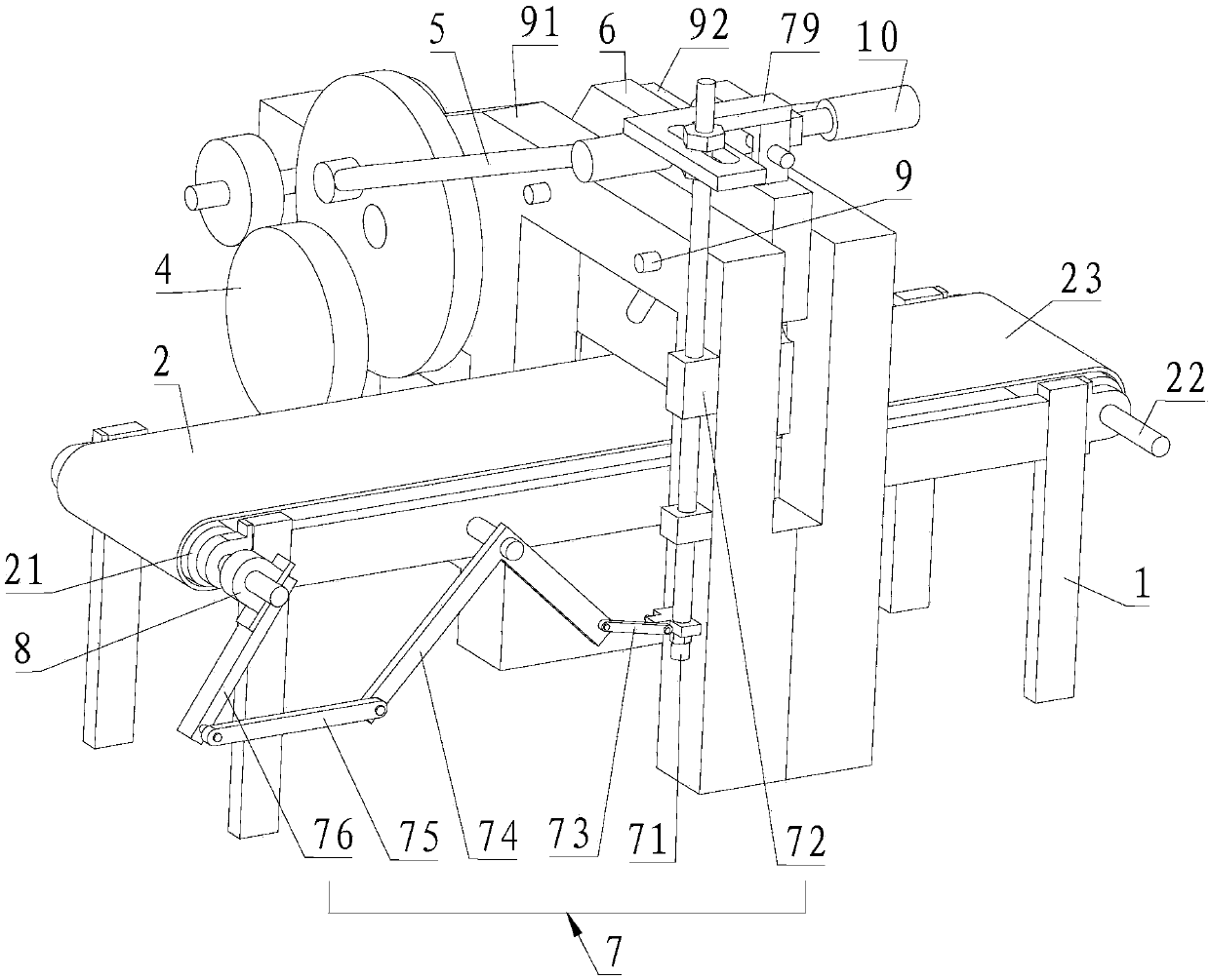
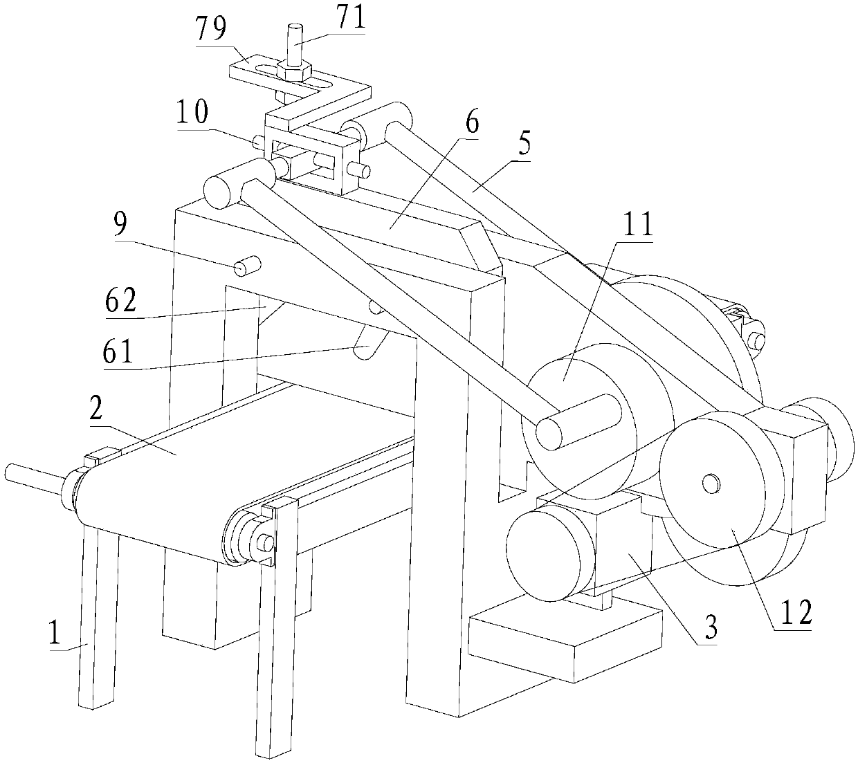
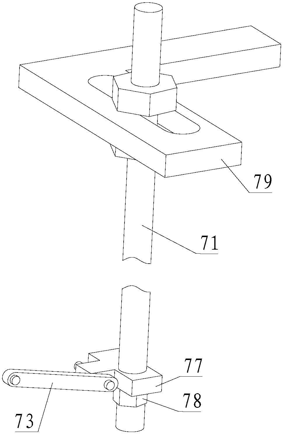
[0041] Please refer to Figure 1 to Figure 4 , The first embodiment of the present invention is:

[0042] A film cutting device includes a frame 1, a conveyor belt assembly 2, and the conveyor belt assembly 2 includes a first roller 21, a second roller 22, and a conveyor belt 23. The conveyor belt 23 is sleeved on the first roller 21 And on the second roller 22, it also includes a motor 3, a gear transmission assembly 4, a tie rod 5, a cutter 6, a link mechanism 7, a one-way bearing 8, a cutter positioning guide 9, a tie rod adjustment assembly 10, and a driven wheel 11. , Belt drive assembly 12, the output shaft of the motor 3 is connected to the input end of the gear drive assembly 4, one end of the pull rod 5 is eccentrically connected to the gear drive assembly 4, and the other end is connected to the cutter 6 The upper end is rotatably connected, the cutter 6 is located above the conveyor belt 23, the input end of the linkage mechanism 7 is connected to the upper end of the...


PUM


Abstract

The invention provides a film cutting device, which includes a frame and a conveyor belt assembly, the conveyor belt assembly includes a first roller, a second roller and a conveyor belt, and the conveyor belt is sleeved on the first roller and the second roller On the shaft, it also includes a motor, a gear transmission assembly, a pull rod, a cutter, a linkage mechanism and a one-way bearing. The output shaft of the motor is connected to the input end of the gear transmission assembly, and one end of the pull rod is connected to the gear transmission assembly. The assembly is eccentrically connected, and the other end is connected to the upper end of the cutter, and the cutter is located above the conveyor belt. The input end of the linkage mechanism is connected to the upper end of the cutter, and the output end passes through the single The bearing is connected with the first roller, and the motor is fixed on the frame. The motor drives the cutter to move up and down through the gear transmission assembly and the pull rod, and drives the first roller to rotate intermittently through the connecting rod mechanism and one-way bearing to realize two actions of film cutting and material feeding. The system is simple and saves energy.

Description

Technical field [0001] The invention relates to the technical field of film cutting equipment, in particular to a film cutting device. Background technique [0002] The film cutting device mainly needs to complete two actions: feeding and film cutting. Most of the existing film cutting devices separate the feeding and cutting power sources. For example, the Chinese Utility Model Patent Publication No. CN202716525U discloses a film cutting device. The motor drives the conveyor belt to move, and the hot cutting knife is fixed at the bottom end of the lower beam. The lower beam moves vertically reciprocating relative to the upper beam, and the cylinder drives the lower beam to move relative to the upper beam. Although it has the advantages of independent control of feeding and film cutting and convenient maintenance, it requires two power sources: cylinder and motor. Installation of pneumatic system is complicated and consumes much energy. Summary of the invention [0003] The tech...

Claims


Application Information

Patent Timeline
IPC IPC(8): B65H20/06B65H35/06B65G23/04B65G23/38B65G23/24
CPCB65G23/04B65G23/24B65G23/38B65H20/06B65H35/06B65H2701/1752B65H2301/44322
Inventor 王友炎戚健
Owner 王友炎
Why Eureka
Try Eureka