Ultralow-temperature cryogenic top-entry ball valve with built-in pressure release valve

A pressure relief valve, ultra-low temperature technology, applied in the direction of cocks, valve details, safety valves, etc. including cut-off devices, can solve the problems of low reliability, achieve high reliability, avoid uncertainty, reasonable structure and stable effect

Pending Publication Date: 2021-08-03
FUJIAN PROVINCE DATONG RECIPROCITY VALVE CO LTD
View PDF0 Cites 2 Cited by
  • Summary
  • Abstract
  • Description
  • Claims
  • Application Information

AI Technical Summary

Problems solved by technology

[0013] The purpose of the present invention is to solve the shortcomings of low reliability of the self-relieving function of the traditional cryogenic ball valve in the prior art, and propose an ultra-low temperature cryogenic top-mounted ball valve with a built-in pressure relief valve

Method used


Image

  • Ultralow-temperature cryogenic top-entry ball valve with built-in pressure release valve
  • Ultralow-temperature cryogenic top-entry ball valve with built-in pressure release valve
  • Ultralow-temperature cryogenic top-entry ball valve with built-in pressure release valve

Examples


Embodiment 1

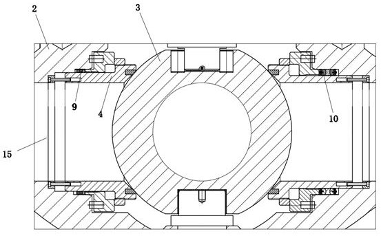
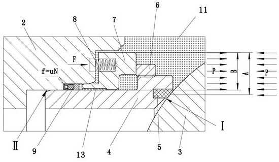
[0028] refer to Figure 1-4 , an ultra-low temperature cryogenic top-loading ball valve with a built-in pressure relief valve, comprising a valve body 2, a fluid passage 15 and a valve stem passage interconnected in the valve body 2, a ball 3 arranged in the fluid passage 15, and a valve stem passage One end away from the fluid channel 15 is covered with a bonnet, the valve stem channel is provided with a valve stem, the side of the valve stem close to the fluid channel is connected to the sphere 3, and the end of the valve stem away from the sphere 3 passes through the valve stem channel and passes out of the valve. A valve seat 4 is respectively installed between the two sides of the sphere 3 and the valve body 2, the upstream end of the valve seat 4 is provided with a two-way pan plug 10, and the valve body 2 adjacent to the two valve seats 4 is provided with a The one-way pressure relief valve installation holes 2 for communicating with the fluid channel 15 and the middle ...

Embodiment 2

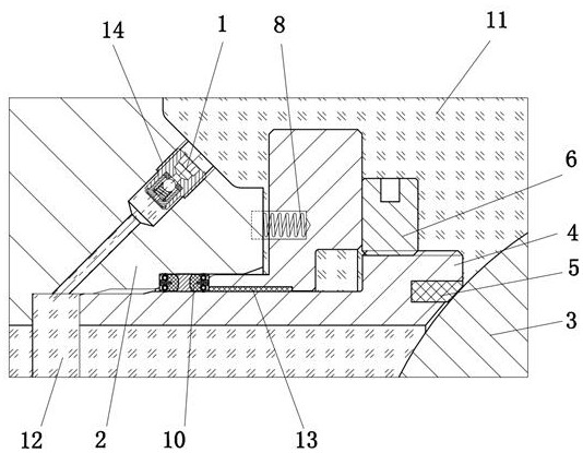
[0032] refer to Figure 1-4, as another preferred embodiment of the present invention, the difference from Embodiment 1 is that Embodiment 1 is suitable for places where the number of opening and closing of cryogenic ball valves installed on the cryogenic pipelines of natural gas liquid plants and LNG receiving stations is relatively frequent, if If the cryogenic ball valve installed in the device system is in a normally open state, this scheme can be selected. The principle is: a one-way drain connected to the fluid passage 15 is designed on the upper part of the ball 3 adjacent to the two valve seats 4. Pressure valve 1. Because the valve installed in the cryogenic device system is normally open, the abnormally elevated pressure in the middle cavity can be released into the channel. Among them, when the size of the ball is Sφ86~Sφ135mm, the one-way pressure relief valve of 1 / 8-27NPT can be selected; when the size of the ball is Sφ135~Sφ250mm, the one-way pressure relief val...


PUM


Abstract

The invention relates to the technical field of mechanical engineering valves, in particular to an ultralow-temperature cryogenic top-entry ball valve with a built-in pressure release valve. A fluid channel and a valve rod channel which are communicated with each other are formed in a valve body; a ball body is arranged in the fluid channel; the end, far away from the fluid channel, of the valve rod channel is covered with a valve cover; a valve rod is arranged in the valve rod channel; the side, close to the fluid channel, of the valve rod is connected with the ball body; the end, away from the ball body, of the valve rod penetrates through the valve rod channel and penetrates out of the valve cover; a valve seat is mounted between each of the two sides of the ball body and the valve body respectively; a one-way pressure release valve mounting hole used for communicating the fluid channel and a middle cavity is formed in the position, adjacent to the two valve seats, of the valve body; and a one-way pressure release valve matched with the one-way pressure release valve mounting hole is mounted in each one-way pressure release valve mounting hole. The one-way pressure release valves are arranged to release an abnormal pressure boosting medium in a valve cavity, so that the uncertainty existing when the valve seats automatically release pressure through the area difference is avoided, and the reliability is high.

Description

technical field [0001] The invention relates to the technical field of mechanical engineering valves, in particular to an ultra-low temperature cryogenic top loading ball valve with a built-in pressure relief valve. Background technique [0002] Cryogenic top-loading ball valves are widely used as switching devices on cryogenic pipelines in natural gas liquid plants and LNG receiving stations due to their compact structure, small overall valve height, and on-line maintenance functions. [0003] However, the cryogenic ball valve used in cryogenic conditions will retain a part of the medium during the opening and closing process. When the valve is in the fully open or fully closed position, the trapped medium is sealed in a closed cavity by the upstream and downstream sealing rings. , when the temperature rises, gasification occurs, and the volume increases by about 625 times. The pressure of these media will rise sharply in a limited space, and there is a potential risk of fa...

Claims


Application Information

Patent Timeline
IPC IPC(8): F16K5/06F16K5/08F16K39/06
CPCF16K5/06F16K5/08F16K17/0406F16K39/06
Inventor 张清双李俊吴健健
Owner FUJIAN PROVINCE DATONG RECIPROCITY VALVE CO LTD
Why Eureka
Try Eureka