Rotating type opening and closing garbage storage device
A garbage storage and rotating technology, which is applied in garbage collection, trash cans, household appliances, etc., can solve the problems of not installing a sealing protection cover, affecting the beauty of the indoor environment, polluting the indoor environment, etc., to ensure a good environment and not easy to emit odors , the effect of simple operation
- Summary
- Abstract
- Description
- Claims
- Application Information
AI Technical Summary
Problems solved by technology
Method used
Image
Examples
Embodiment 1
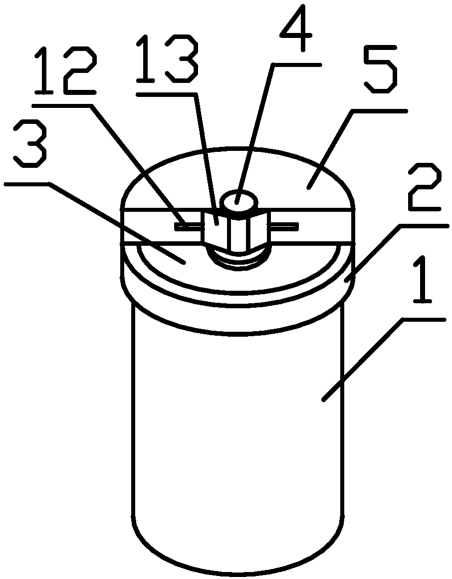
[0026] Such as Figure 1~3 As shown, the present invention provides a rotary opening and closing garbage storage device, which includes a vertical cylinder 1 with a closed bottom and an open top. It also includes a cylindrical protective cover 2, the protective cover 2 is set on the open end of the cylinder 1, the end face of the protective cover 2 is provided with a fan-shaped notch 3, and the arc center of the fan-shaped notch 3 is connected with the protective cover 2 axis coincides. A rotating shaft 4 protrudes from the axial center of the end surface of the protective cover 2 , and the rotating shaft 4 is rotationally connected with the end surface of the protective cover 2 . A rotating cover 5 is also provided on the rotating shaft 4 . The rotating cover 5 has a semicircular structure, and the axis of the rotating cover 5 is fixedly connected with the rotating shaft 4 . By applying external force to the rotating cover 5 and driving the rotating shaft 4 to rotate relati...
Embodiment 2
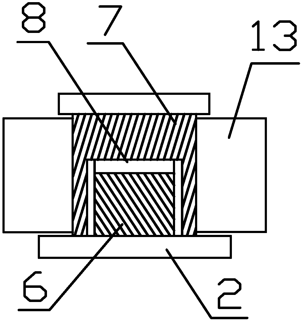
[0028] Further improvement on the basis of Embodiment 1, the rotating shaft 4 includes a fixed column 6 and a movable sleeve 7, one axial end of the fixed column 6 is fixed at the axial center of the end face of the protective cover plate 2, and a rotary joint 8 is provided at the other end. The movable sleeve 7 is sleeved on the fixed column 6 , the inner sidewall of the movable sleeve 7 is in clearance fit with the outer sidewall of the fixed column 6 , and the inner bottom surface of the movable sleeve 7 is connected with the rotary joint 8 . The movable sleeve 7 is rotationally connected with the fixed column 6 through the rotary joint 8 ; the outer wall of the movable sleeve 7 is connected with the rotating cover 5 .
Embodiment 3
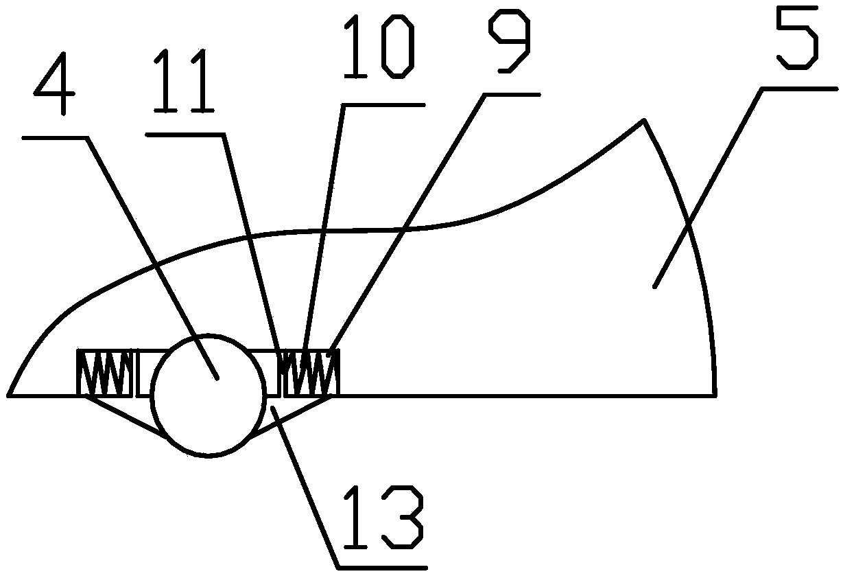
[0030] Further improvement on the basis of Embodiment 2, two mirror-symmetric limiting grooves 9 are provided on the radial side wall of the rotating cover 5, and a spring 10 is arranged in the limiting groove 9, and one axial end of the spring 10 Fixed on the inner wall of the limit groove 9, the other end is provided with a slide bar 11, the axial free end of the slide bar 11 extends out of the chute 12 on the side wall of the rotating cover 5, and the protruding end of the slide bar 11 is provided with a pressure block 13 . In the state of use, the spring 10 is compressed, and under the restoring force of the spring 10 , the rotating shaft 5 is compressed and fixed between the two pressing blocks 13 . A layer of rubber pad is glued on the contact surface between the pressure block 13 and the rotating shaft 5 .
PUM
 Abstract
Description
Claims
Application Information
 - R&D
- Intellectual Property
- Life Sciences
- Materials
- Tech Scout
- Unparalleled Data Quality
- Higher Quality Content
- 60% Fewer Hallucinations
Browse by: Latest US Patents, China's latest patents, Technical Efficacy Thesaurus, Application Domain, Technology Topic, Popular Technical Reports.
© 2025 PatSnap. All rights reserved.Legal|Privacy policy|Modern Slavery Act Transparency Statement|Sitemap|About US| Contact US: help@patsnap.com


