LED display device and method for correcting luminance thereof

A display device and brightness correction technology, applied in lighting devices, static indicators, lamp circuit layout, etc., can solve the problems of brightness reduction and difference, and achieve the effects of reducing power consumption, reducing storage times, and achieving precision

Active Publication Date: 2018-04-17
MITSUBISHI ELECTRIC CORP
View PDF16 Cites 2 Cited by
  • Summary
  • Abstract
  • Description
  • Claims
  • Application Information

AI Technical Summary

Problems solved by technology

However, since the brightness of LEDs decreases as the lighting time becomes longer, the brightness reduction rate of each LED varies depending on the content of the image. As a result, brightness variations and color variations occur for each pixel

Method used


Image

  • LED display device and method for correcting luminance thereof
  • LED display device and method for correcting luminance thereof
  • LED display device and method for correcting luminance thereof

Examples


Embodiment approach 1

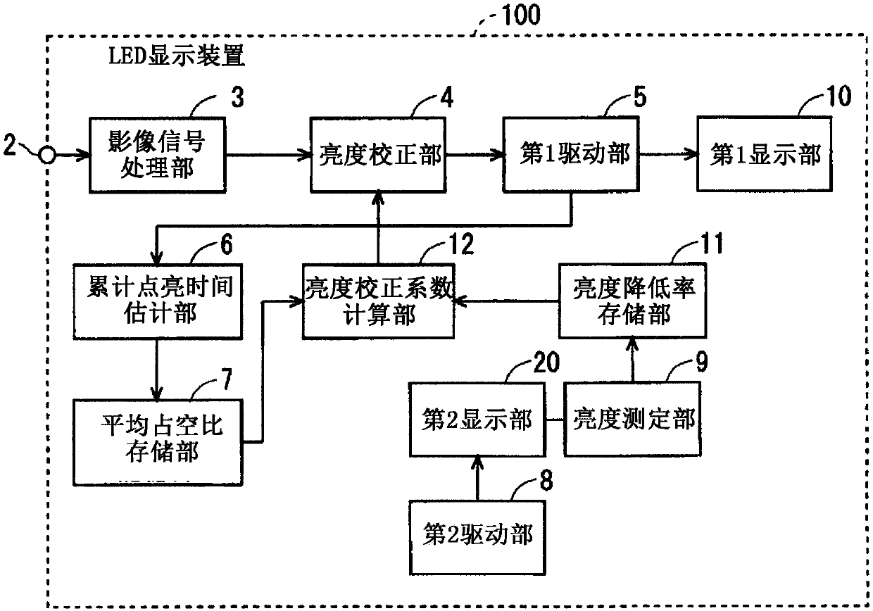
[0027] figure 1 It is a functional block diagram of the LED display device 100 of the first embodiment. Such as figure 1 As shown, the LED display device 100 has a first display unit 10, a first drive unit 5, a second display unit 20, a second drive unit 8, a luminance measurement unit 9, a luminance reduction rate storage unit 11, and a cumulative lighting time estimation unit. 6. The average duty ratio storage unit 7 , the brightness correction coefficient calculation unit 12 and the brightness correction unit 4 .

[0028] The first display unit 10 has a plurality of unit pixels arranged in a matrix of M rows and N columns. M rows and N columns are, for example, 4 rows and 4 columns, but not limited thereto. Three LED elements of red (R), green (G), and blue (B) are arranged in each unit pixel.

[0029] The first drive unit 5 drives the plurality of LED elements included in the first display unit 10 based on the video signal received from the video signal processing unit...

Embodiment approach 2

[0123] In Embodiment 1, it is assumed that during the unit operating time, the current duty ratio R 1 Drive the LED element to calculate the second cumulative lighting time S 1 (Refer to formula 2).

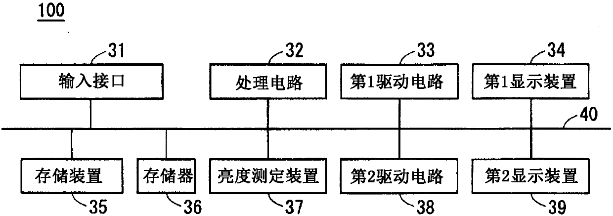
[0124] In Embodiment 2, in order to calculate the second cumulative lighting time S with higher accuracy 1 , using the average duty ratio R stored in the average duty ratio storage unit 7 0 and the duty cycle of the current moment R 1 Calculate the second cumulative lighting time S from the duty cycle obtained by arithmetic mean 1 . In addition, the structure of the LED display device 100 of the second embodiment is the same as that of the first embodiment ( figure 1 , figure 2 ) are the same, so the description is omitted. In Embodiment 2, the second cumulative lighting time S 1 It is represented by the following formula 9.

[0125] [Formula 9]

[0126]

[0127] The calculation method of the first cumulative lighting time in Embodiment 2 is the same as that in Embodi...


PUM


Abstract

The purpose of the present invention is to provide: an LED display device for correcting the luminance of each LED element while reducing the amount of calculation and amount of data stored required for calculating the lighting time of each LED element; and a method for correcting the luminance of the LED display device. This LED display device 100 comprises: a first display unit 10 including a plurality of LED elements; a second display unit 20 including measurement LED elements identical to the LED elements of the first display unit 10; a luminance measurement unit 9 for measuring the luminance of the measurement LED elements; a luminance degradation rate storage unit 11 for storing a degradation rate in the luminance of the measurement LED elements; an accumulated lighting time estimation unit 6 for estimating an accumulated lighting time at each predetermined time interval; an average duty ratio storage unit 7 for storing an average duty ratio calculated by dividing the accumulatedlighting time estimated by an accumulated operation time; and a luminance correction coefficient calculation unit 12 for calculating a luminance degradation rate by referring to the luminance degradation rate storage unit 11 and the average duty ratio storage unit 7, and calculating a luminance correction coefficient from the luminance degradation rate.

Description

technical field [0001] The present invention relates to an LED display device and a brightness correction method thereof, and more particularly to an LED display device that displays image information by controlling blinking of a plurality of LEDs (Light Emitting Diodes: Light Emitting Diodes) arranged in a matrix. Background technique [0002] With the technological development and cost reduction of LEDs, display devices made of LEDs are more widely used in outdoor and indoor advertising displays and the like. These LED display devices have previously been dominated by dynamic image displays of natural images and animations. In recent years, as the pixel pitch has been narrowed, the visual observation distance has been shortened, and it has been applied to meeting rooms, monitoring purposes, and the like. Especially in surveillance applications, personal computer images that are close to static images are increasingly displayed. However, since the luminance of LEDs decrea...

Claims


Application Information

Patent Timeline
Patent Type & Authority Applications(China)
IPC IPC(8): G09G3/32G09G3/20G09G3/34H01L33/00H05B37/02
CPCG09G3/32G09G3/3225G09G2320/0233G09G2320/0242G09G2320/029G09G2320/043G09G2320/045G09G2320/048G09G2360/145G09G2360/16G02F1/00G09G3/20G09G3/34H01L33/00G09G2310/0264
Inventor 的场隆志涉江重教浅村吉范
Owner MITSUBISHI ELECTRIC CORP
Why Eureka
Try Eureka