
Image processing method and its device

An image processing and image technology, which is applied in the directions of image data processing, image analysis, image communication, etc., can solve the problem of large amount of processing

Inactive Publication Date: 2006-09-13
PANASONIC CORP
View PDF2 Cites 0 Cited by
  • Summary
  • Abstract
  • Description
  • Claims
  • Application Information

AI Technical Summary

Problems solved by technology

[0017] However, when performing target detection by template matching, since pixel data such as luminance signals and color difference signals are used as input processing, when processing images compressed and encoded by MPEG, etc., template matching processing must be performed for each frame after decoding processing. There is a problem with high processing volume

Method used


Image

  • Image processing method and its device
  • Image processing method and its device
  • Image processing method and its device

Examples


Embodiment approach 1

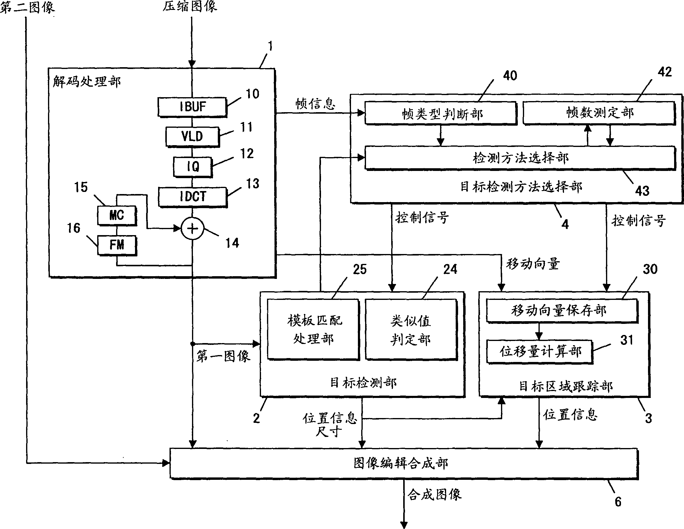
[0050] figure 1 is a block diagram of the image processing device according to Embodiment 1 of the present invention.

[0051] Such as figure 1 As shown, the image processing device includes: a decoding processing unit 1 , an object detection unit 2 , an object area tracking unit 3 , an object detection method selection unit 4 and an image editing and synthesis unit 6 .

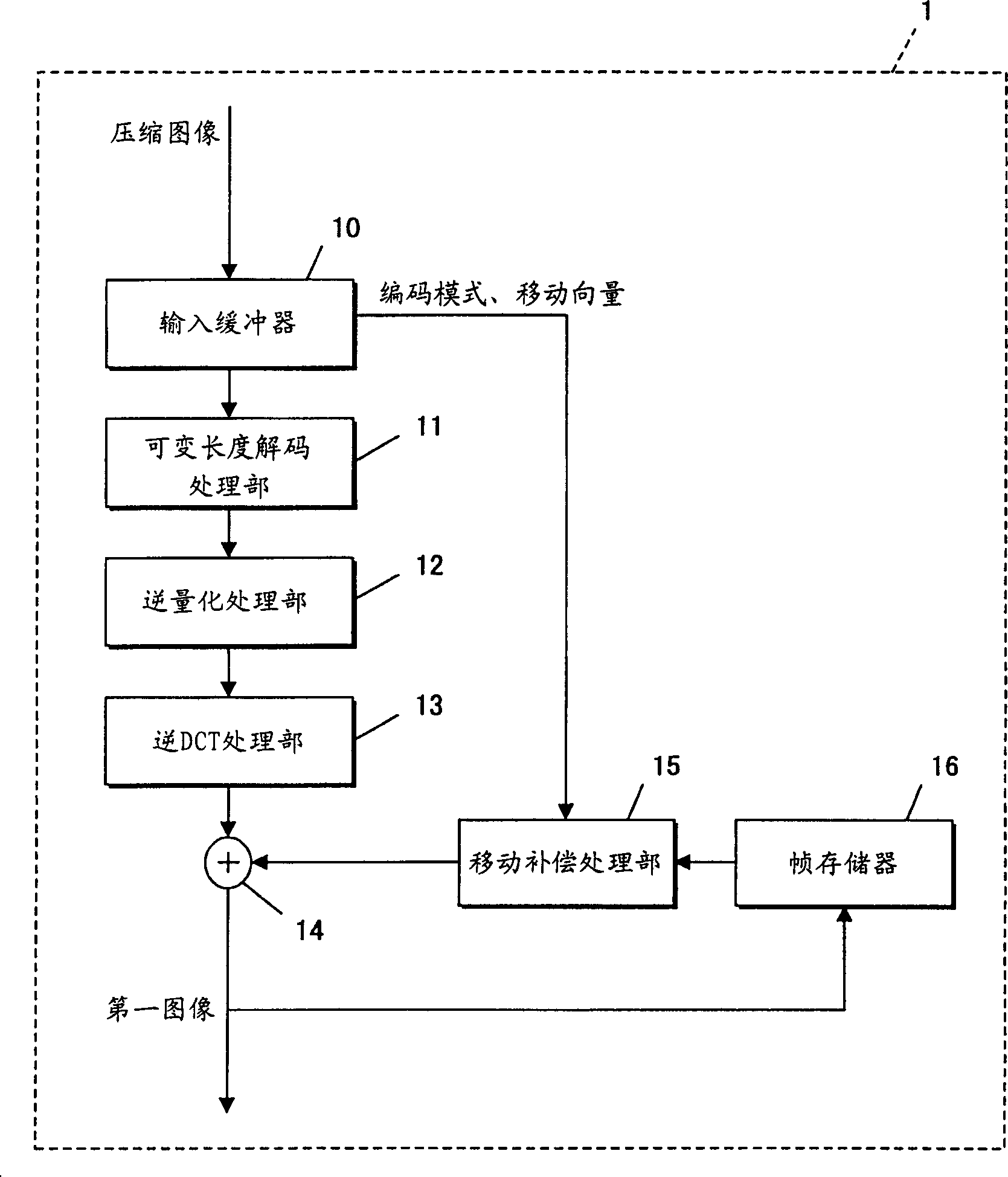
[0052] The decoding processing part 1 includes: an input buffer (IBUF) 10, a variable length decoding processing part (VLD) 11, an inverse quantization processing part (IQ) 12, an inverse discrete cosine transform processing part (IDCT) 13, an addition processing part 14, motion compensation processing unit (MC) 15 and frame memory (FM) 16 .

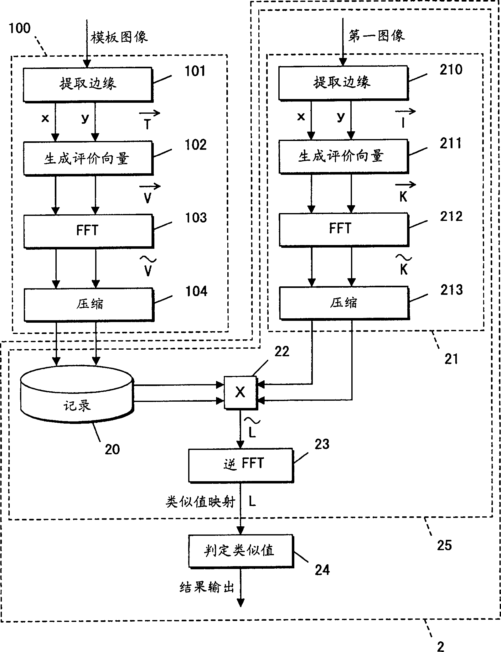
[0053] The object detection processing unit 2 includes a template matching processing unit 25 and a similarity value determination unit 24 .

[0054] The target area tracking unit 3 includes a motion vector storage unit 30 and a displacement calculation unit 31 .

...

Embodiment approach 2

[0215] 8 is a block diagram of an image processing device according to Embodiment 2 of the present invention. For Figure 8 with figure 1 The same parts are assigned the same symbols, and explanations are appropriately omitted.

[0216] As shown in FIG. 8 , the image processing device includes: an object detection unit 2 , an object area tracking unit 3 , an image editing and synthesis unit 6 , a scene change detection unit 5 , a detection method selection unit 7 and an encoding processing unit 8 .

[0217] Coding processing section 8 comprises: subtraction processing section 80, discrete cosine transform processing section (DCT) 81, quantization processing section (Q) 82, variable length coding processing section (VLC) 83, inverse quantization processing section (IQ) 84, An inverse discrete cosine transform processing unit (IDCT) 85 , an addition processing unit 86 , a frame memory (FM) 87 , a motion compensation processing unit (MC) 88 , and a motion vector detection unit (M...


PUM


Abstract

Image processing method and its device. A domain of an object detected by template matching is tracked in accordance with information on a motion vector that is included in compressed and encoded data. This feature eliminates template matching-based object detection when it comes to a motion vector information-containing image subject to object detection. As a result, object detection is achievable with a less amount of processing, when compared with the template matching-based detection of objects in all images subject to object detection.

Description

technical field [0001] The present invention relates to an image processing method and apparatus for detecting a target (object) from an input image. Background technique [0002] Conventionally, a technique of registering a template image in advance, performing pattern matching between the input image and the template image, and detecting the position of an image similar to the template image in the input image is well known. [0003] However, regardless of the background of an image similar to the template image, misrecognition is likely to occur. A technique to solve this problem is disclosed in JP-A-5-28273. Among them, the similarity value between the template image and the image corresponding to the template image is defined by the following formula. [0004] 【Formula 1】 [0005] σ S 0 = 1 MN Σ i ...

Claims


Application Information

Patent Timeline
Patent Type & Authority Patents(China)
IPC IPC(8): G06K9/62G06K9/28G06T7/20H04N19/50G06T7/00G06V30/144H04N5/14H04N19/20H04N19/27H04N19/503H04N19/577H04N19/593H04N19/61H04N19/625H04N19/80H04N19/91
CPCG06T7/20G06T7/0044G06T7/74G06V40/167
Inventor 片冈知典梶田哲史渕上郁雄今川和幸岩佐克博
Owner PANASONIC CORP
Learn More