
Rubber continuous vulcanization system

A vulcanization system and rubber vulcanization technology, applied in the field of rubber continuous vulcanization system, can solve the problems of cleaning costs, inability to handle, and increased air volume.

Pending Publication Date: 2021-05-21
NISHIKAWA RUBBER +1
View PDF3 Cites 0 Cited by
  • Summary
  • Abstract
  • Description
  • Claims
  • Application Information

AI Technical Summary

Problems solved by technology

[0004] According to this structure, although the sulfide gas does not scatter and the temperature does not drop, there are problems in the following problems: checking the foaming state, slack state, posture, passing position of the object to be heated, and correction of the position or posture , processing when an exception occurs, and other operations cannot be performed
In order to prevent this situation, it is effective to regularly clean the grease dirt M, but it requires cleaning costs
It is also possible to check the degree of accumulation of grease and dirt M inside the pipe 6 and clean it as necessary, but it is not easy to check the inside of the pipe 6 in terms of structure
In addition, it is also possible to set the suction volume assuming that the ventilation area is narrow at the start of the vulcanization equipment operation, but it also becomes expensive due to the increase in the air volume for deodorization.

Method used


Image

  • Rubber continuous vulcanization system
  • Rubber continuous vulcanization system
  • Rubber continuous vulcanization system

Examples


Embodiment Construction

[0082] Next, a continuous rubber vulcanization system 100 according to an embodiment of the present invention will be described with reference to the drawings.

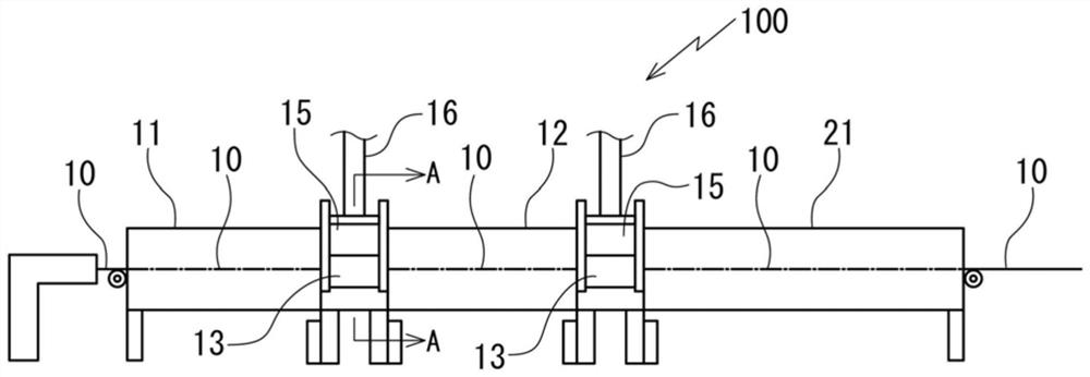
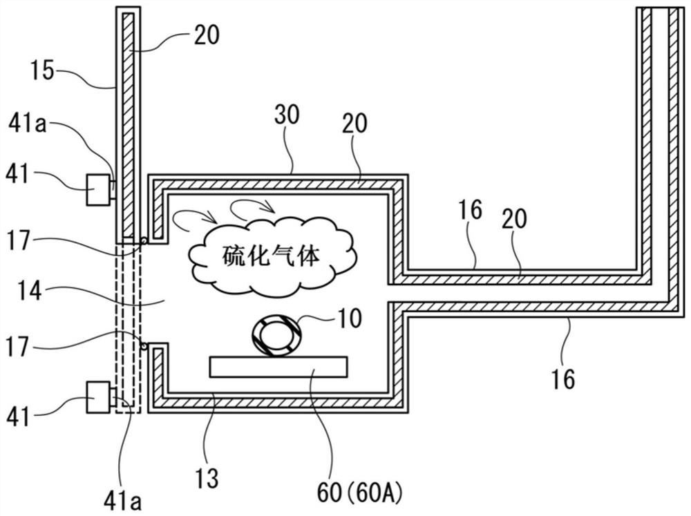
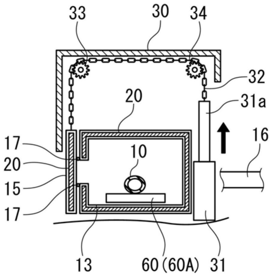
[0083] The rubber continuous vulcanization system 100 such as figure 1 As shown, a plurality of vulcanization furnaces 11 and 12 continuously arranged in series are connected by a connecting body (a cylinder in this embodiment, but not particularly limited) 13 to cover the gap between the vulcanization furnaces 11 and 12 live. The vulcanization furnaces (vulcanization tanks) 11 and 12 are microwave heating furnaces that irradiate microwaves to an object to be heated (workpiece) 10 to vulcanize. In addition, the vulcanization furnace 21 installed in series downstream of the vulcanization furnace 12 is a hot-air heating furnace that blows hot air on the workpiece 10 to vulcanize it. As the workpiece 10, for example, a weather strip for automobiles is assumed.

[0084] Such as figure 2 As shown, an inspection port ...


PUM


Abstract

The present invention provides a continuous rubber vulcanization system which can perform inspection and work while preventing scattering of vulcanization gas, and has excellent heat preservation performance. In a rubber vulcanizing furnace (11, 12) in which a plurality of grooves are continuously arranged, the front and back of the grooves or space between the grooves are covered by a connecting body (13) provided with a heat insulation wall (20) and an exhaust duct (16), and vulcanizing gas generated by a workpiece (10) in the grooves and the connecting body (13) is sucked through the exhaust duct (16). The amount of intake air in the exhaust duct (16) is reduced in response to the amount of sulfide gas that diffuses into the atmosphere being suppressed, thereby taking into account environmental protection.

Description

technical field [0001] The invention relates to a continuous rubber vulcanization system provided with a plurality of vulcanization furnaces in series. Background technique [0002] Conventionally, if there is nothing between the vulcanization furnaces installed in series (for example, Patent Document 1), vulcanization gas is freely scattered in the air, which may cause environmental pollution and influence on the human body. In addition, for example, objects to be heated (workpieces) such as weather strips for automobiles are air-cooled between vulcanization furnaces, so there is a problem that the vulcanization state deteriorates and the quality of the objects to be heated deteriorates. Furthermore, there is also a problem that dirt called grease scale tends to adhere to the opening of the vulcanization equipment when the high-temperature vulcanization gas is cooled. [0003] Therefore, there is known a configuration in which adjacent vulcanization furnaces are directly i...

Claims


Application Information

Patent Timeline
IPC IPC(8): B29C35/06B29C35/10B29C35/00
CPCB29C35/045B29C35/06B29C35/0805B29C35/10B29C35/00B29C2035/0855
Inventor 宫田晃小川秀树山中亨
Owner NISHIKAWA RUBBER
Learn More