Electric Motor and Method for Manufacturing an Electric Motor

Active Publication Date: 2009-05-28
SEW-EURODRIVE GMBH & CO KG
View PDF12 Cites 22 Cited by
  • Summary
  • Abstract
  • Description
  • Claims
  • Application Information

AI Technical Summary

Benefits of technology

[0005]Example embodiments of the present invention provide a device and a method by which the manufacture of an elec

Problems solved by technology

The large mass and thus costly manufa

Method used


Image

  • Electric Motor and Method for Manufacturing an Electric Motor
  • Electric Motor and Method for Manufacturing an Electric Motor
  • Electric Motor and Method for Manufacturing an Electric Motor

Examples


Embodiment Construction

[0034]The motor according to example embodiments of the present invention includes a stator made up at least of tooth segments.

[0035]FIGS. 4 through 11 show the manufacturing steps of the fully wound tooth segment in order.

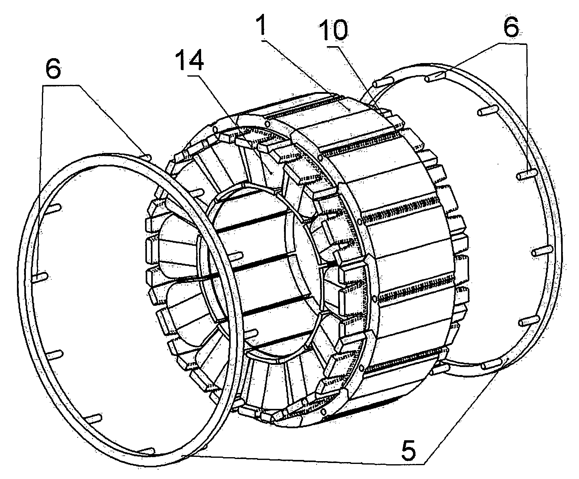
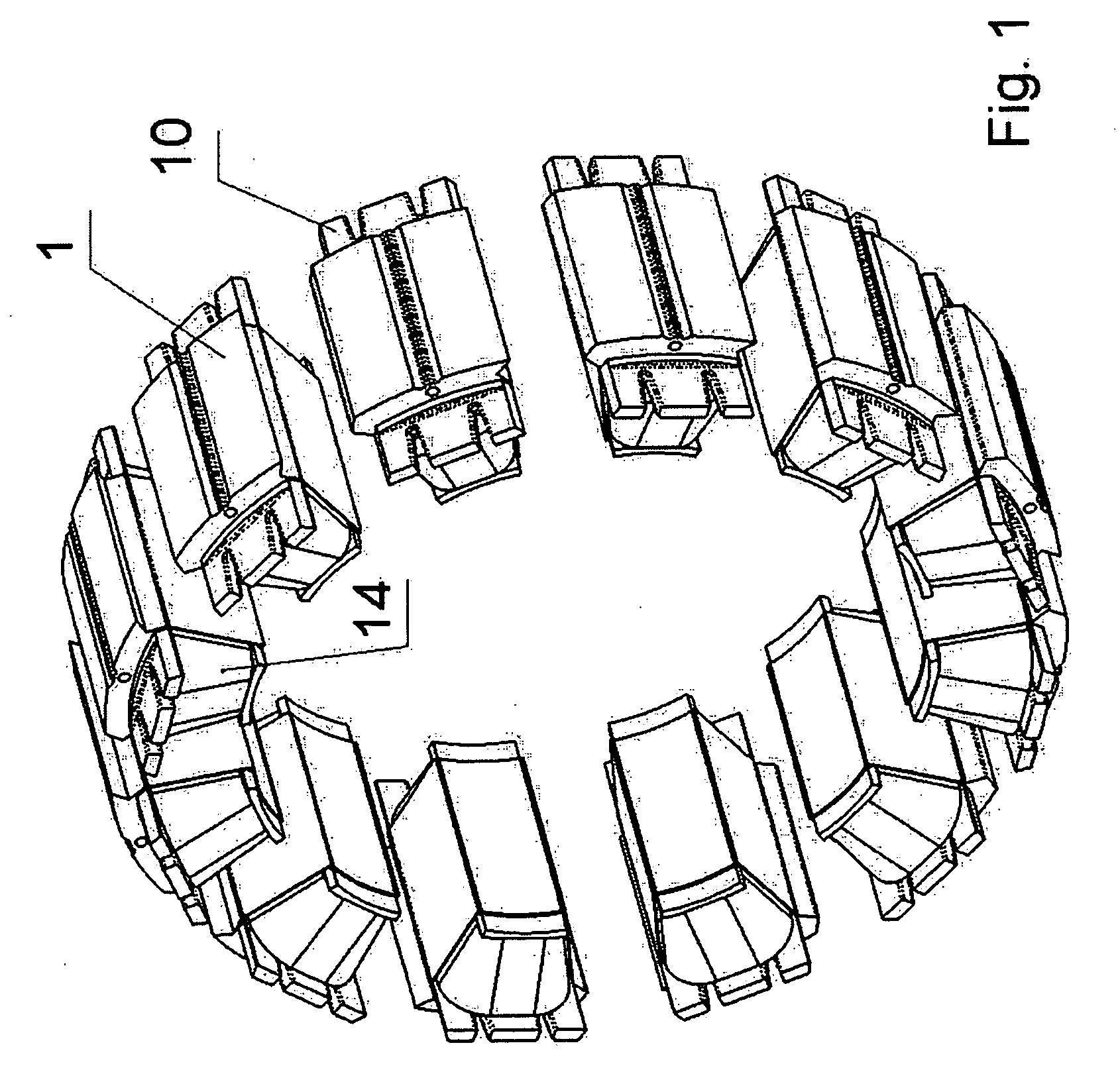
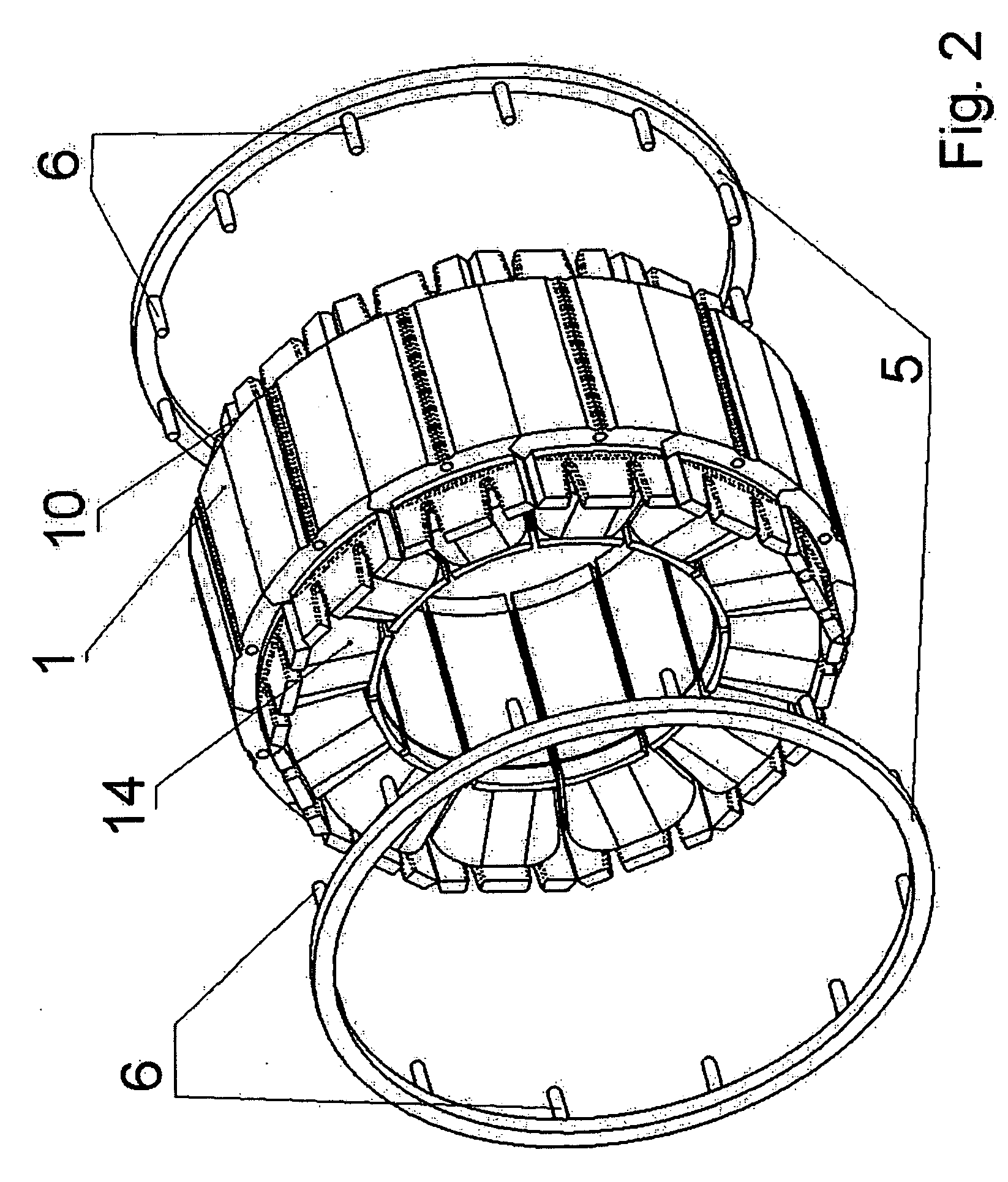
[0036]FIGS. 1 through 3 show the assembly of the stator from the tooth segments.

[0037]In the following, the figures are explained in more detail in sequence.

[0038]FIG. 4 shows a tooth segment 1. It has a groove 4 and a tongue 3 and a projection 8 produced by the stamp-packing process. In addition, a hole is provided for inserting pegs 6.

[0039]FIG. 5 show the insulating paper 9 that is slid onto the tooth segment.

[0040]FIG. 6 shows tooth segment 1 having insulating paper 9 slid onto it.

[0041]FIG. 7 shows an end cap 10, which has grooves 12 for guiding wires and a coil support 11 for securing the winding and recesses as wire guides 13.

[0042]FIG. 8 shows a tooth segment having slid-on end caps 10.

[0043]FIG. 9 shows a tooth segment subsequently wound by winding 14.

[00...


PUM


Abstract

An electric motor, includes a stator, which is composed at least of stamp-packed tooth segments, the tooth segments being able to be slid together radially in the manufacture and being able to be held together by retaining elements slid on axially.

Description

FIELD OF THE INVENTION[0001]The present invention relates to an electric motor and a method for manufacturing an electric motor.BACKGROUND INFORMATION[0002]European Published Patent Application No. 1 322 021 describes a stator in which the teeth of the stator are axially inserted into a hollow cylindrical annular body. Caps, having electrical plug connections, are plugged onto both ends. The large mass and thus costly manufacture of the motor is a disadvantage.[0003]U.S. Pat. No. 6,226,856 also describes a stator in which the teeth of the stator are inserted axially into one another.[0004]U.S. Pat. No. 6,359,355 describes a stator in which the segments are indeed brought together radially, but they are retained by a surrounding “circular pattern 28”.SUMMARY[0005]Example embodiments of the present invention provide a device and a method by which the manufacture of an electric motor and an associated series may be simplified and by which the protection of the environment may be improv...

Claims


Application Information

Patent Timeline
IPC IPC(8): H02K1/18H02K15/02
CPCH02K1/148H02K1/185Y10T29/49009H02K3/522H02K15/022H02K3/325
Inventor RHODE, STEPHAN
Owner SEW-EURODRIVE GMBH & CO KG
Why Eureka
Try Eureka