Gait tester

A tester and gait technology, applied in the field of sports medicine analysis, can solve the problems of large volume of marking points, limited number of marking points, long preparation time, etc., and achieve the effect of improving the quality of analysis

Inactive Publication Date: 2018-05-08
阿尔法迈士医疗科技(上海)有限公司
View PDF8 Cites 2 Cited by
  • Summary
  • Abstract
  • Description
  • Claims
  • Application Information

AI Technical Summary

Problems solved by technology

There are many obvious defects in this method, such as: long preparation time; it requires a lot of manpower; the analysis is mainly subjective and the accuracy is low; the data obtained is less; clinical reports are filled in manually, which is time-consuming, laborious and error-prone
[0004] 2. Video method: the process of human walking is captured by video equipment (CCD camera), and then the lattice analysis is performed frame by frame. The advantage is that the equipment is simple and the gait of the subjects is relatively natural. Relying on manual work requires relatively high operating requirements and relatively large errors, and only two-dimensional plane analysis can be performed, and the accuracy of three-dimensional spatial analysis cannot be guaranteed
Its advantages are that the equipment is relatively cheap, the operation is relatively simple, and the data is relatively accurate; however, ultrasonic waves are easy to reflect, and the interference of surrounding objects must be eliminated, and the requirements for the surrounding environment are high. The number of points is limited, and it is only suitable for segmental analysis of human body
[0007] Gait measurement is an important method in sports medicine, but due to current methods, it is difficult to accurately and effectively collect data in a real walking environment

Method used


Image

  • Gait tester
  • Gait tester

Examples


Embodiment Construction

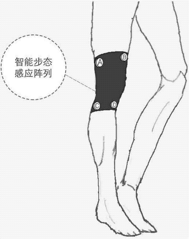
[0023] Gait tester of the present invention, as figure 1 As shown, it includes a protective gear, which is similar to knee pads, and is worn by the user at the knee joint to wrap the knee joint. The first to fourth four gait data sensors are fixed on the protective gear. Wherein the first and second gait data sensors are respectively located on the left and right sides above the knee joint (corresponding to A and B gait data sensors in the figure respectively), and the third and fourth gait data sensors are respectively located on the left and right sides below the knee joint (respectively corresponding to the C and D gait data sensors in the figure), and the four sensors are all located on the outer side of the legs; the distance between the four gait data sensors is relatively fixed. Wherein, the distance between the first and second gait data sensors positioned above the knee is 4 centimeters (i.e. the distance between A and B), and the distance between the third and fourth...


PUM


Abstract

The invention discloses a gait tester. The gait tester comprises protective clothing, the protective clothing is worn by a user at the knee joints, so that the knee joints are covered. Four gait datasensors are fixed to the gait clothing, wherein the first gait data sensor and the second gait data sensor are located at the left side and the right side above the knees respectively, the third gaitsensor and the fourth gait sensor are located at the left side and the right side below the knees respectively, and all the four gait sensors are located on the outer side faces of the legs; the distance of the four gait data sensors is relatively fixed. Each of the four gait sensors comprises an MCU, a six-axis gyroscope, a position sensor, a gravity acceleration senor and a Bluetooth communication device, and is supplied with power through a button cell. By means of the tester which is worn on the user, relevant data of the knee joints when the user walks in daily life can be collected, andthrough analysis of the data, analysis of the scientificity of the walking gait of the user and the possible long-term influence of the walking gait on the knee joint can be promoted.

Description

technical field [0001] The present invention relates to the analysis of sports medicine, in particular to a gait tester, which collects and analyzes the data of the knee joint movement during the user's walking or running to determine the pressure on the knee joint, and analyzes the possible impact of the user's walking style on the knee joint. long-term impact. Background technique [0002] Walking (or running) is the most common form of exercise, and gait measurement is used to assess, plan, and treat an individual's ability to walk. In particular, gait analysis is the basis of treatment. Combining the collection of walking posture of patients with leg injuries or diseases with kinematics, biology, and neural reconstruction and remodeling, it is beneficial to give a reasonable treatment plan and the use of corresponding treatment equipment. . The main method of gait analysis is to use protective gear with colored punctuation on the human body, such as knee pads, to walk ...

Claims


Application Information

Patent Timeline
IPC IPC(8): A61B5/11
CPCA61B5/112A61B5/6802
Inventor 钱景鸿
Owner 阿尔法迈士医疗科技(上海)有限公司
Why Eureka
Try Eureka