Waste heat recovery for power generation and engine warm-up

A waste heat recovery, engine technology, applied in the direction of engine starting, engine components, combustion engines, etc., can solve the problems of increasing system cost and packaging space

Active Publication Date: 2022-01-11
FORD GLOBAL TECH LLC
View PDF6 Cites 0 Cited by
  • Summary
  • Abstract
  • Description
  • Claims
  • Application Information

AI Technical Summary

Problems solved by technology

Such systems, separate from the waste heat recovery system, typically require at least a heat exchanger, a heating circuit, and several control valves, which increases system cost and packaging space

Method used


Image

  • Waste heat recovery for power generation and engine warm-up
  • Waste heat recovery for power generation and engine warm-up
  • Waste heat recovery for power generation and engine warm-up

Examples


Embodiment Construction

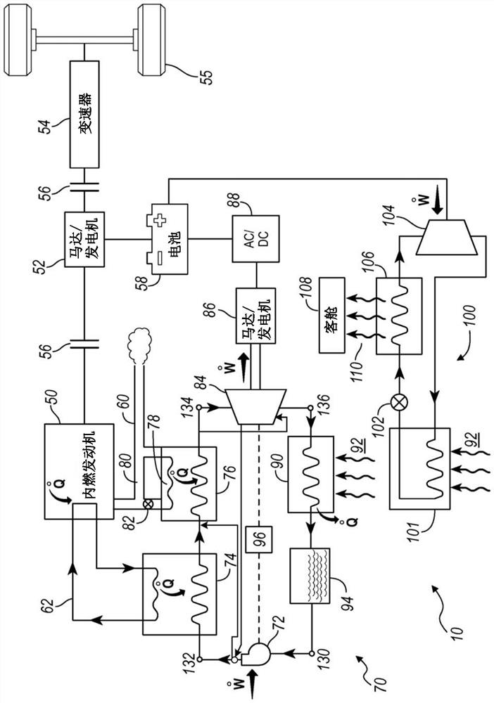
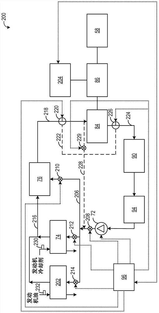
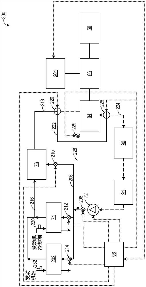
[0013] The Rankine cycle can be used to convert thermal energy into mechanical power or electricity. Efforts have been made to harvest thermal energy more efficiently or from more than one system that exhausts heat from the vehicle (such as engine coolant, engine or transmission oil, exhaust gas recirculation (EGR) gases, exhaust, etc.) waste heat. The present disclosure provides a waste heat recovery system for a Rankine cycle that is configured to operate in a warm-up mode or an engine cooling mode in addition to operating in a power generation mode. This is accomplished by including an additional working fluid flow path in the system and comprising a first flow path coupling the outlet of the evaporator to the outlet of the expander, and a second flow path A path couples the inlet of the expander to the outlet of the pump. During standard power generation mode, the expander operates in the forward direction to expand and extract mechanical energy from the working fluid, w...


PUM


Abstract

The present invention relates to waste heat recovery for power generation and engine preheating. Methods and systems are provided for heating an engine and generating energy from a shared waste heat recovery system. In one example, a method includes: expanding a working fluid of the waste heat recovery system via an expander to generate electricity in response to a first condition; and compressing the working fluid of the waste heat recovery system via an expander to transfer heat in response to a second condition to the engine.

Description

technical field [0001] The present specification generally relates to methods and systems for controlling a waste heat recovery system to simultaneously generate electricity and warm an engine. Background technique [0002] Waste heat recovery systems for vehicles recover heat energy from engine exhaust, engine coolant, engine oil and / or transmission fluid that would otherwise be dissipated into the surrounding environment. Waste heat recovery systems typically include heat exchanger(s) to absorb heat from engine coolant, engine oil and / or transmission fluid, an evaporator to heat the working fluid, an expander to generate mechanical work ( expander), a condenser to cool the working fluid and a pump to push the working fluid back to the heat exchanger(s). The mechanical work can then be converted to energy for storage in the vehicle battery, for example via a generator. [0003] An exemplary waste heat recovery system is shown by Zhou in US Patent Application Publication N...

Claims


Application Information

Patent Timeline
Patent Type & Authority Patents(China)
IPC IPC(8): F02G5/04F01K23/10F02N19/10
CPCF01K23/10F02G5/04F02N19/10F01K15/02F01K23/101F01K23/065F01N5/02Y02T10/12F02G5/02F05D2220/62H02K7/1823
Inventor 周时光
Owner FORD GLOBAL TECH LLC
Why Eureka
Try Eureka