Novel power supply plug device

A new type of power supply plug-in technology, which is applied to the parts of the connecting device, coupling devices, circuits, etc., can solve the problems of power supply seat safety hazards, electric shock accidents, children's injuries, etc. High security and the effect of reducing potential safety hazards

Active Publication Date: 2018-05-18
海盐金隆照明科技股份有限公司
View PDF4 Cites 34 Cited by
  • Summary
  • Abstract
  • Description
  • Claims
  • Application Information

AI Technical Summary

Problems solved by technology

[0002] With the application level of power technology and the improvement of living standards, the number of electrical equipment used in households is increasing, and there are more and more types of household appliances. More and more, when the traditional plug is matched with the power supply seat, it usually relies on friction to maintain the power supply state. When this kind of plug is accidentally bumped, it is easy to cause the plug to loosen or fall off. Therefore, it is easy to cause a sudden power failure. Phenomenon, it is easy to cause a certain impact on the electrical equipment, and in the traditional power supply seat, the power supply piece is connected with the outer end, because of the curiosity of children, they will use the external metal rod or metal piece to insert into the power supply When these metal rods or metal sheets are inserted into the power supply seat, they will be in contact with the power supply sheet, so the metal rods or metal sheets will be directly connected to the mains. Therefore, this operation will cause electric shock accidents and will harm children. Cause different degrees of injury, in severe cases, it will endanger life safety, therefore, there is a great potential safety hazard in the traditional power supply stand

Method used


Image

  • Novel power supply plug device
  • Novel power supply plug device
  • Novel power supply plug device

Examples


Embodiment Construction

[0021] All features disclosed in this specification, or steps in all methods or processes disclosed, may be combined in any manner, except for mutually exclusive features and / or steps.

[0022] Any feature disclosed in this specification (including any appended claims, abstract and drawings), unless expressly stated otherwise, may be replaced by alternative features which are equivalent or serve a similar purpose. That is, unless expressly stated otherwise, each feature is one example only of a series of equivalent or similar features.

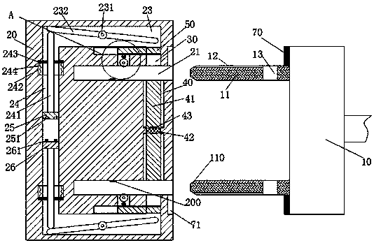
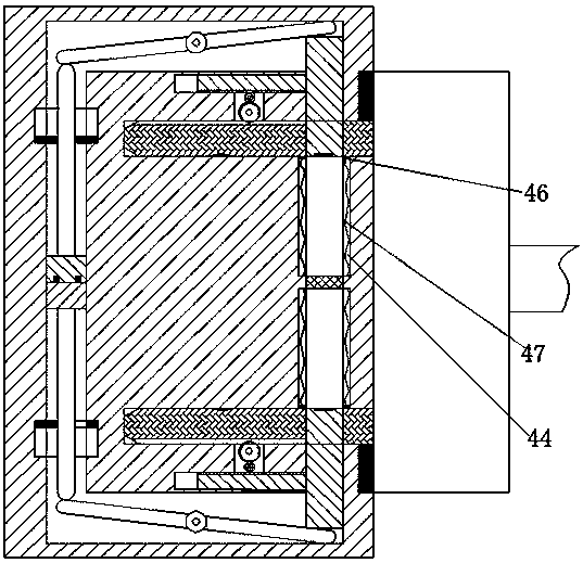
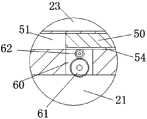
[0023] Such as Figure 1-3 As shown, a new type of power supply plug-in device of the device of the present invention includes a power supply base 20 fixedly installed in the wall and a plug 10 connected to household appliances, and the power supply base 20 is symmetrically provided with jacks with openings facing the right. 21. The power supply base 20 is provided with a swing groove 23 symmetrically up and down outside the socket 21, and th...


PUM


Abstract

The invention discloses a novel power supply plug device. The novel power supply plug device comprises a power supply seat and a plug and is characterized in that the power supply seat is fixedly arranged in a wall, the plug is connected with a household electrical appliance, jacks are vertically and symmetrically arranged in the power supply seat and are provided with rightward openings, swinginggrooves are vertically and symmetrically arranged in positions, at outer sides of the jacks, in the power supply seat, first sliding grooves are arranged in positions, at left sides of the jacks, inthe power supply seat and communicate with the swinging grooves, second sliding grooves are arranged between the two jacks in the power supply seat and are provided with openings facing the jacks, toppress rods are rotatably arranged in the swinging grooves by hinge shafts, sliding rods are arranged in the first sliding grooves and prop against the top press rods in a matching way, a power supplyson block is fixed at the bottom of the sliding rod at an upper side, and a power supply mother block is fixed at the top of the sliding rod at a lower side.

Description

technical field [0001] The invention relates to the field of electrical power supply and electricity utilization, in particular to a novel power supply plug-in device. Background technique [0002] With the application level of power technology and the improvement of living standards, the number of electrical equipment used in households is increasing, and there are more and more types of household appliances. More and more, when the traditional plug is matched with the power supply seat, it usually relies on friction to maintain the power supply state. When this kind of plug is accidentally bumped, it is easy to cause the plug to loosen or fall off. Therefore, it is easy to cause a sudden power failure. Phenomenon, it is easy to cause a certain impact on the electrical equipment, and in the traditional power supply seat, the power supply piece is connected with the outer end, because of the curiosity of children, they will use the external metal rod or metal piece to insert...

Claims


Application Information

Patent Timeline
Patent Type & Authority Applications(China)
IPC IPC(8): H01R13/639H01R13/70
CPCH01R13/639H01R13/701
Inventor 马浩晓
Owner 海盐金隆照明科技股份有限公司
Why Eureka
Try Eureka