Carrying trolley rotating mechanism of vertical lifting type stereo garage and carrying trolley
A technology for three-dimensional parking garages and transporting trolleys, which is applied in the field of transporting trolley rotation mechanisms and transporting trolleys, can solve problems such as the bad influence of the control of the rotary drive components, the rotation of the turntable, etc., and achieve the protection of the rotary drive components, stable and simple control Effect
- Summary
- Abstract
- Description
- Claims
- Application Information
AI Technical Summary
Problems solved by technology
Method used
Image

Examples
Embodiment Construction
[0021] The present invention will be described in further detail below in conjunction with the accompanying drawings and specific embodiments.
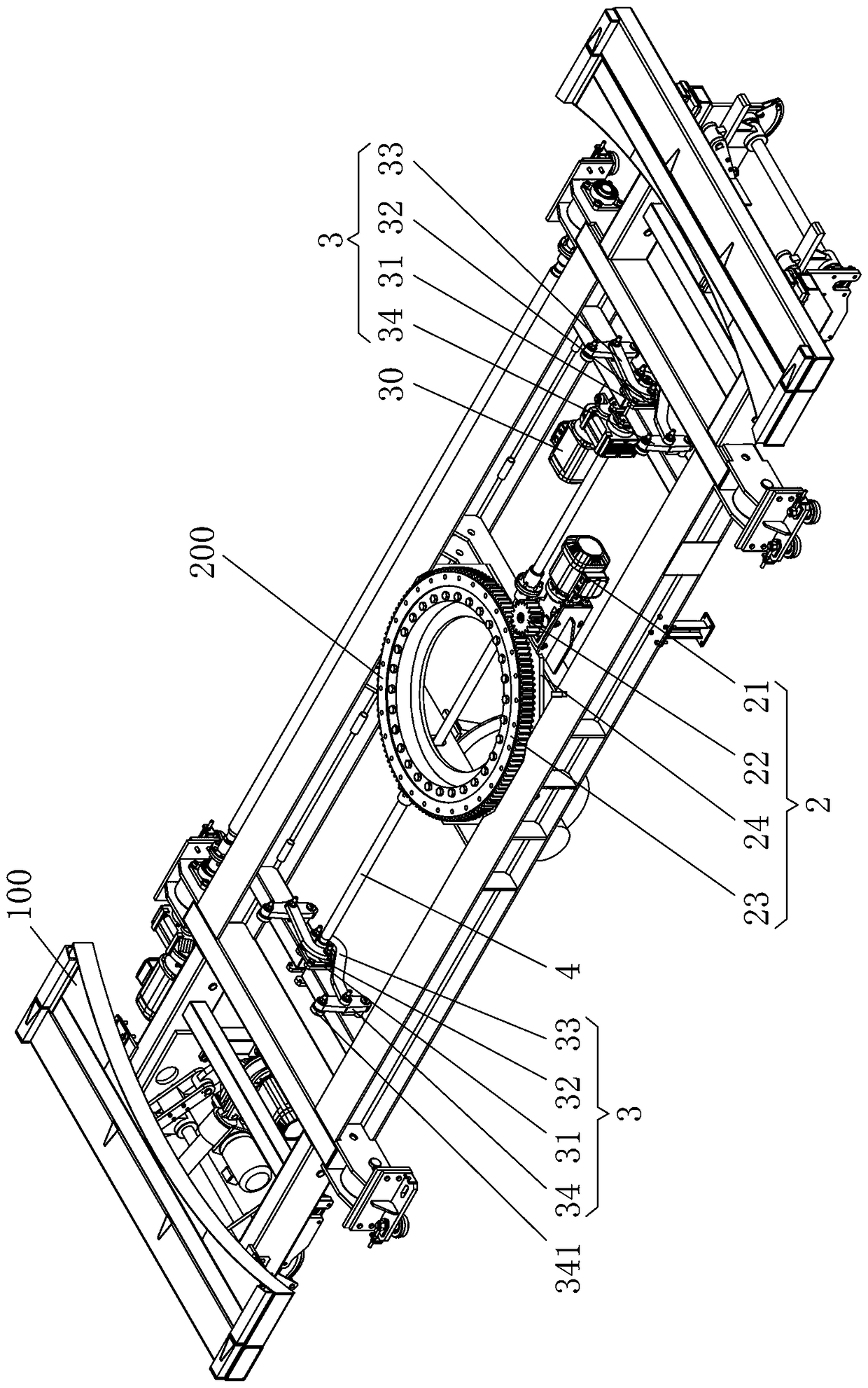
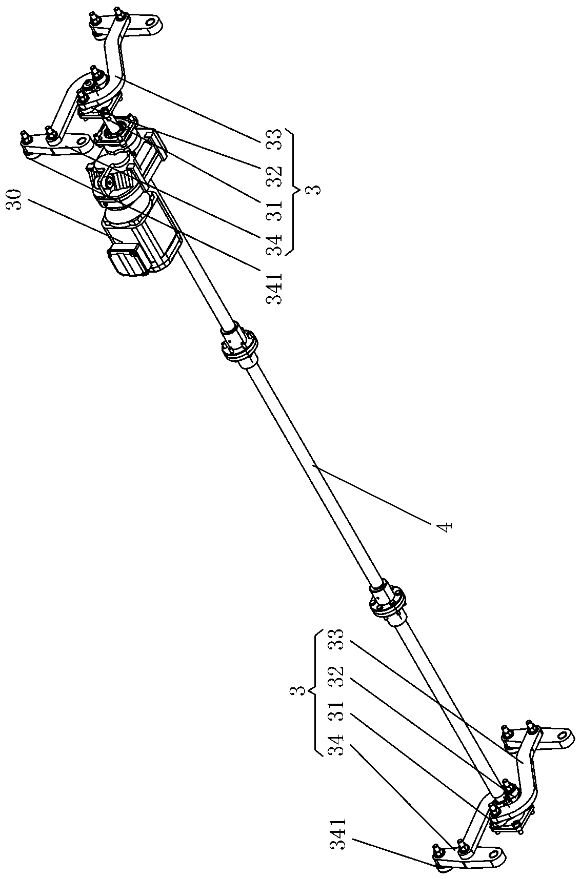
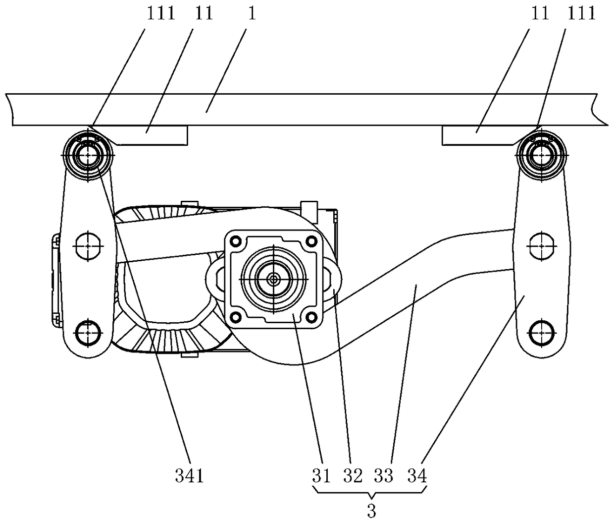
[0022] like Figure 1 to Figure 3 As shown, the transport trolley rotation mechanism of the vertical lifting three-dimensional parking garage of this embodiment includes a turntable 1, a rotation drive assembly 2 and a locking assembly 3, and the rotation drive assembly 2 is installed in the middle of the transport trolley 100, and is located at Below the turntable 1, the turntable 1 is connected to the rotation output end of the rotary drive assembly 2, the locking assembly 3 is located below the turntable 1 and installed on the transport trolley 100, and the locking end of the locking assembly 3 forms a lock with the turntable 1 Works with unlock. The transfer trolley rotation mechanism of the vertical lift type three-dimensional parking garage of the present invention can realize the U-turn and reversing of the vehicle on the tran...
PUM
 Abstract
Description
Claims
Application Information
 - Generate Ideas
- Intellectual Property
- Life Sciences
- Materials
- Tech Scout
- Unparalleled Data Quality
- Higher Quality Content
- 60% Fewer Hallucinations
Browse by: Latest US Patents, China's latest patents, Technical Efficacy Thesaurus, Application Domain, Technology Topic, Popular Technical Reports.
© 2025 PatSnap. All rights reserved.Legal|Privacy policy|Modern Slavery Act Transparency Statement|Sitemap|About US| Contact US: help@patsnap.com