Hydraulic inserted pin lifting device

A lifting device and hydraulic technology, applied in the field of marine engineering equipment, can solve the problem that the self-elevating offshore platform cannot be continuously raised and lowered

Inactive Publication Date: 2018-06-01
WUHAN MARINE MACHINERY PLANT
View PDF7 Cites 5 Cited by
  • Summary
  • Abstract
  • Description
  • Claims
  • Application Information

AI Technical Summary

Problems solved by technology

[0006] In order to solve the problem that the self-elevating offshore platform cannot be continuously raised

Method used


Image

  • Hydraulic inserted pin lifting device
  • Hydraulic inserted pin lifting device
  • Hydraulic inserted pin lifting device

Examples


Embodiment Construction

[0023] In order to make the object, technical solution and advantages of the present invention clearer, the implementation manner of the present invention will be further described in detail below in conjunction with the accompanying drawings.

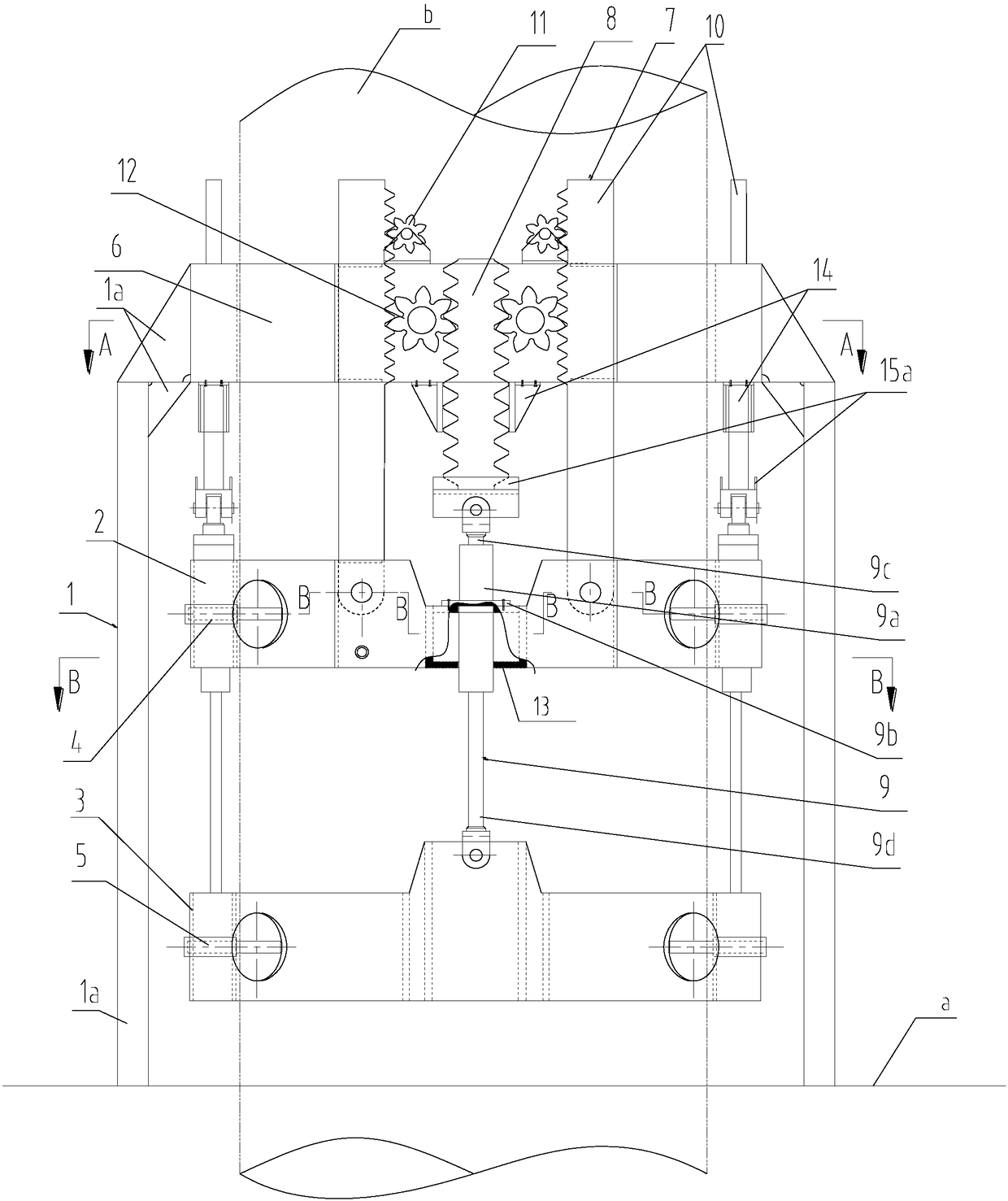
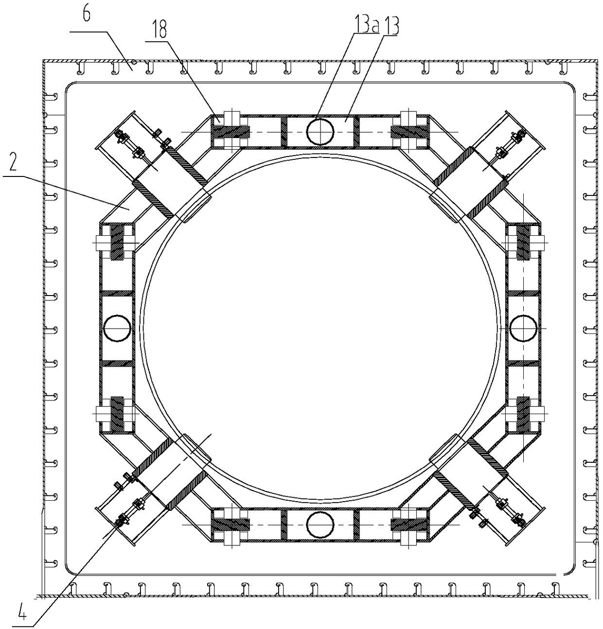
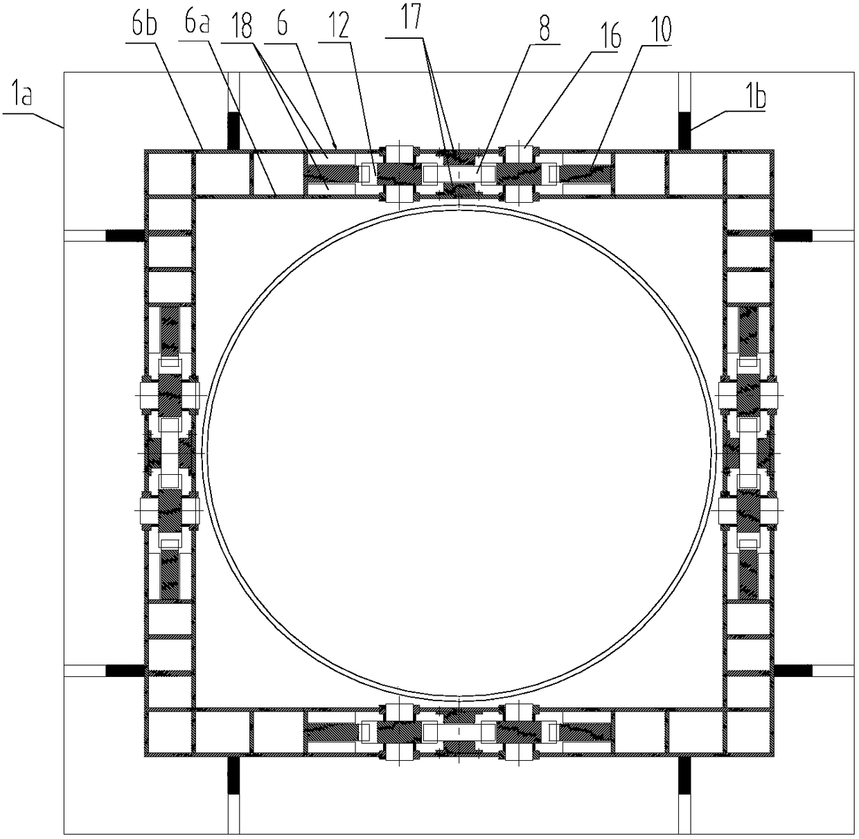
[0024] The embodiment of the present invention provides a hydraulic bolt lifting device, the hydraulic bolt lifting device includes: a pile frame 1, a first ring beam 2, a second ring beam 3, a first ring beam bolt assembly 4 and a second ring beam bolt Component 5,. The first ring beam latch assembly 4 is installed on the first ring beam 2 , and the second ring beam latch assembly 5 is installed on the second ring beam 3 .

[0025] The pile-fixing frame 1 includes a pile-fixing frame ring beam 6, the pile-fixing frame ring beam 6, the first ring beam 2 and the second ring beam 3 are coaxially and sequentially arranged at intervals, and the hydraulic bolt lifting device also includes at least two lifting devices 7, At least two liftin...


PUM


Abstract

The invention discloses a hydraulic inserted pin lifting device, and belongs to the field of marine engineering equipment. The hydraulic inserted pin lifting device comprises a pile fixing bracket, afirst ring beam, a second ring beam, a first ring beam inserted pin assembly and a second ring beam inserted bin assembly, wherein the pile fixing bracket comprises a pile fixing bracket ring beam; and the pile fixing bracket ring beam, the first ring beam and the second ring beam are coaxially arranged at intervals in sequence. The hydraulic inserted pin lifting device also comprises at least twolifting devices, wherein the at least two lifting devices are arranged at intervals around pile legs; each lifting device comprises a power toothed bar, a supporting oil cylinder, two lifting toothedbars, two lifting gears, two driving gears and two driving assemblies. The hydraulic inserted pin lifting device has the beneficial effects that a self-lifting type marine platform depends on the driving gears and the lifting gears to continuously crawl and lift on the lifting toothed bars and the power toothed bar to and fro so as to realize continuous lifting.

Description

technical field [0001] The invention relates to the field of marine engineering equipment, in particular to a hydraulic bolt lifting device. Background technique [0002] The hydraulic bolt lifting device is a commonly used lifting device for self-elevating offshore platforms. [0003] An existing hydraulic bolt lifting device mainly includes: pile legs, a moving ring beam, a fixed ring beam and a lifting cylinder. The movable ring beam and the fixed ring beam are connected by a lifting cylinder, the movable ring beam and the fixed ring beam are respectively sleeved on the pile legs, and the fixed ring beam is connected to the self-elevating offshore platform through a solid pile frame. The pile legs are provided with pin holes along the length direction, and the movable ring beam and the fixed ring beam are respectively provided with a bolt assembly inserted into the pile leg and a bolt assembly of the fixed ring beam. The lifting action of the self-elevating offshore pla...

Claims


Application Information

Patent Timeline
IPC IPC(8): E02B17/08
CPCE02B17/0809E02B17/0818
Inventor 毛炳坤程文池田崇兴朱正都王鑫磊龚云何鹏赵世琏陈佳俊
Owner WUHAN MARINE MACHINERY PLANT
Why Eureka
Try Eureka