A small catheter tip machine

A small catheter and pointed technology, applied in the field of small catheter pointed machine, can solve problems such as a large number of debris and inconvenience, and achieve the effect of simplified steps

Active Publication Date: 2019-11-01
WENZHOU YONG HENG TECH
View PDF6 Cites 0 Cited by
  • Summary
  • Abstract
  • Description
  • Claims
  • Application Information

AI Technical Summary

Problems solved by technology

[0002] In the prior art, the tip of the solid small catheter is generally formed by cutting, and the cutting method will generate a lot of debris, and the cutting knife needs to be replaced frequently, which brings some inconvenience

Method used


Image

  • A small catheter tip machine
  • A small catheter tip machine

Examples


Embodiment Construction

[0011] The present invention will be further described below in conjunction with the accompanying drawings and embodiments.

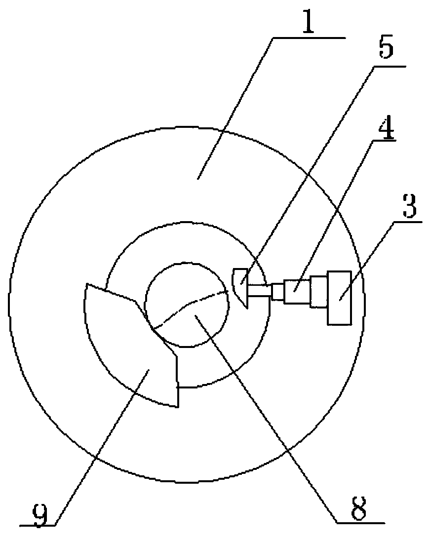
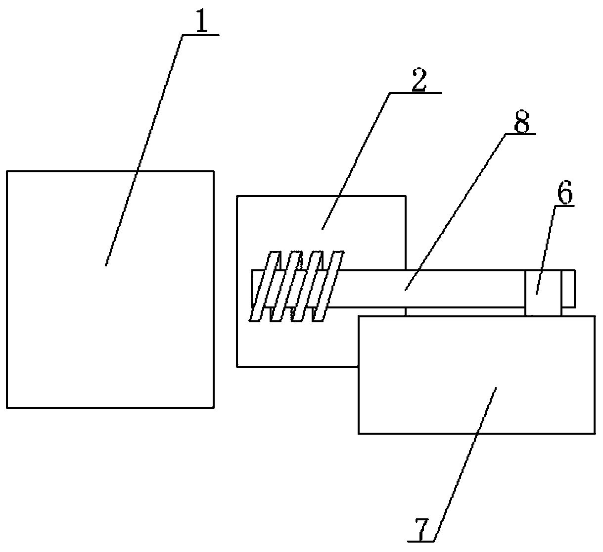
[0012] A small catheter pointing machine, including a fixed plate 1, a lateral adjustment platform for controlling the lateral movement of the catheter 8, a heater 2 located between the lateral adjustment platform and the fixed plate 1, and the heater 2 is used for heating and melting the catheter 8, the middle of the fixed disk 1 is provided with a perforation corresponding to the conduit 8, and the fixed ring is provided with an eccentrically arranged knocking assembly, which includes sequentially connecting the drive pump 3 and the telescopic rod 4 and arc-shaped hammer head 5, the drive pump 3 controls the arc-shaped hammer head 5 to strike the side of the conduit 8 through the telescopic rod 4, and after the knock, the conduit 8 moves to the direction of the eccentric force under the action of the eccentric force One side rotates, thereby makes the...


PUM


Abstract

A small guide pipe end sharpener comprises a fixing plate, a transverse adjusting table for controlling a guide pipe to transversely move, and a heater located between the transverse adjusting table and the fixing plate. The heater is used for heating one end of the guide pipe. A penetrating hole corresponding to the guide pipe is formed in the middle of the fixing plate. An eccentric knocking assembly is arranged on a fixing ring, and comprises a driving pump, a telescopic rod and an arc-shaped hammer which are sequentially connected. The driving pump controls the arc-shaped hammer through the telescopic rod to knock the lateral side of the guide pipe. After knocking, the guide pipe rotates to one side in the direction of eccentric acting force under the effect of the eccentric acting force, and an unknocked part is rotated upward again to the knocking area of the arc-shaped hammer.

Description

technical field [0001] The invention specifically relates to a small catheter tip machine. Background technique [0002] In the prior art, the solid small catheter tip is generally formed by cutting, and the cutting method will generate a lot of debris, and the cutting knife needs to be replaced frequently, which brings some inconvenience. Contents of the invention [0003] In order to solve the above problems, the invention provides a small catheter tip machine: [0004] A small catheter tip machine, including a fixed plate, a lateral adjustment table for controlling the lateral movement of the catheter, a heater located between the lateral adjustment table and the fixed plate, the heater is used to heat the end of the catheter, and the fixed There is a perforation corresponding to the conduit in the middle of the disk, and an eccentrically arranged knocking assembly is provided on the fixed ring. The knocking assembly includes a drive pump, a telescopic rod and an arc-s...

Claims


Application Information

Patent Timeline
Patent Type & Authority Patents(China)
IPC IPC(8): B21D31/06
CPCB21D31/06
Inventor 池希色池希聪池祖国王猛
Owner WENZHOU YONG HENG TECH
Why Eureka
Try Eureka