Optical cavity, optical system and display device

A technology for optical systems and display devices, which is applied in the direction of optics, optical components, light guides of lighting systems, etc., can solve the problems of uneven brightness and darkness of light guide plates, and achieve the effect of improving uneven brightness and darkness

Active Publication Date: 2019-07-09
BOE TECH GRP CO LTD +1
View PDF6 Cites 0 Cited by
  • Summary
  • Abstract
  • Description
  • Claims
  • Application Information

AI Technical Summary

Problems solved by technology

However, due to the limitation of the display device's own conditions such as the light angle of the light source, the phenomenon of uneven brightness (hotspot) appears on the light guide plate.

Method used


Image

  • Optical cavity, optical system and display device
  • Optical cavity, optical system and display device
  • Optical cavity, optical system and display device

Examples


Embodiment Construction

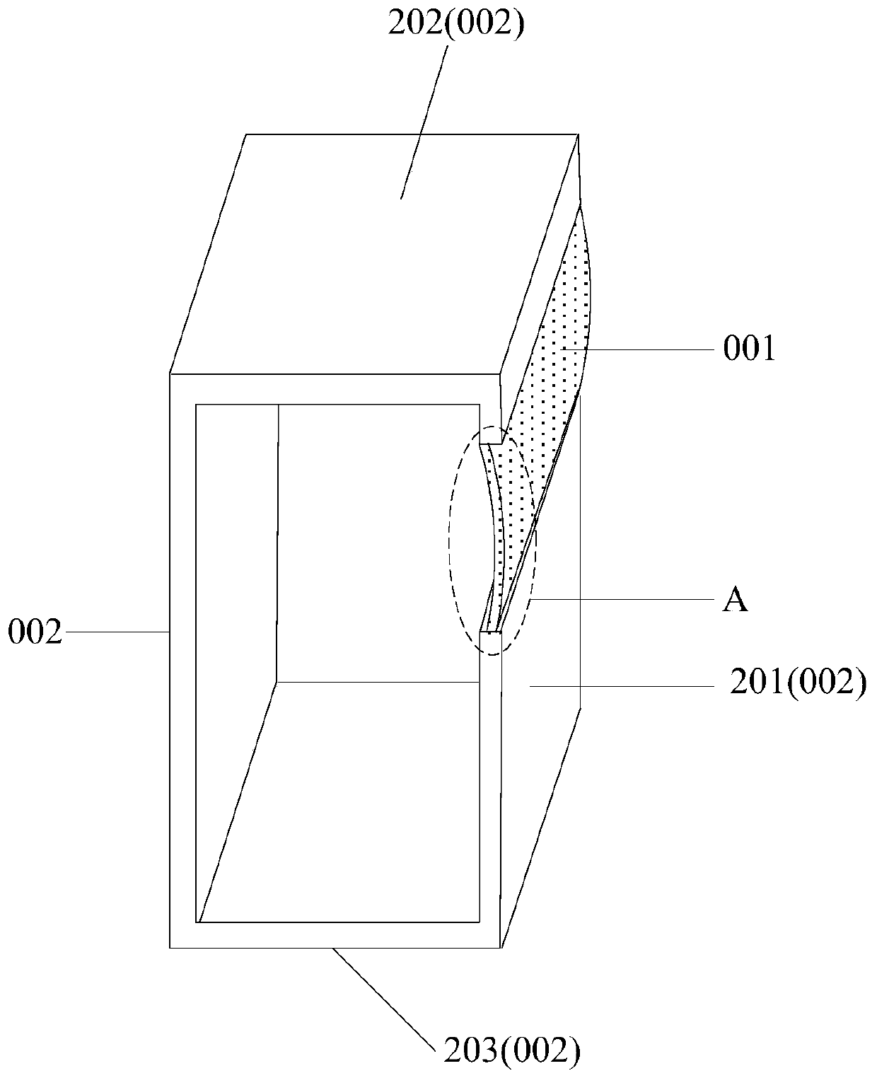
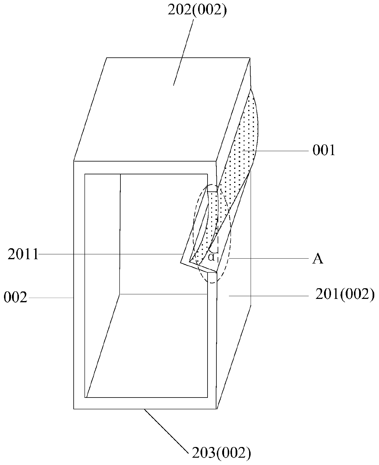
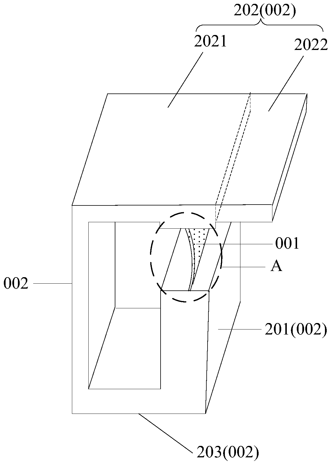
[0031] The specific implementation manners of the optical cavity, the optical system and the display device provided by the embodiments of the present invention will be described in detail below with reference to the accompanying drawings. It should be noted that the embodiments described in this specification are only some of the embodiments of the present invention, not all of them; and in the case of no conflict, the embodiments in this application and the features in the embodiments can be combined with each other; In addition, based on the embodiments of the present invention, all other embodiments obtained by persons of ordinary skill in the art without making creative efforts belong to the protection scope of the present invention.

[0032] The shape and size of each film layer in the drawings do not reflect the real proportion of the optical cavity, and the purpose is only to illustrate the content of the present invention.

[0033] The optical cavity provided by the e...


PUM


Abstract

An optical chamber, an optical system, and a display device are provided. The optical chamber includes: a plurality of sidewalls, including a first sidewall having at least one opening, configured to reflect light in the optical chamber; and a light path adjusting element connected with the first sidewall, wherein the orthographic projection of the light path adjusting element onto the plane where the first sidewall lies at least partially lies in the area where the opening is located, and the light path adjusting element is configured to uniformly emit the light reflected by the plurality of sidewalls to the outside.

Description

technical field [0001] The invention relates to the field of display technology, in particular to an optical cavity, an optical system and a display device. Background technique [0002] With the development of display technology, various display devices such as liquid crystal display devices, plasma display devices, organic light-emitting display devices, and electrophoretic display devices are increasingly occupying various fields. However, due to the limitations of the display device's own conditions such as the light emitting angle of the light source, a phenomenon of uneven brightness (hotspot) appears on the light guide plate. Contents of the invention [0003] In view of this, the embodiments of the present invention provide an optical cavity, an optical system and a display device for improving the phenomenon of uneven brightness and darkness on the light guide plate. [0004] Therefore, an optical cavity provided by an embodiment of the present invention includes...

Claims


Application Information

Patent Timeline
Patent Type & Authority Patents(China)
IPC IPC(8): G02B27/09G02B6/00
CPCG02B6/003G02B6/0031G02B27/0961G02B27/0977G02B6/0028G02B6/0096G02B6/0076
Inventor 梁菲孙凌宇陈秀云杜景军
Owner BOE TECH GRP CO LTD
Why Eureka
Try Eureka